Major update (18/06/2019): added the new SMD version of OpenEMG.
Context
Electromyography (EMG) is an electrodiagnostic medicine technique for evaluating and recording the electrical activity produced by skeletal muscles. An electromyograph detects the electric potential generated by muscle cells when these cells are electrically or neurologically activated.
It can be a useful and intriguing sensor technology to use with Arduino or any other micro-controller. Therefore, I designed the openEMG project, an open-hardware, easy to use and very reliable EMG sensor.
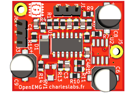
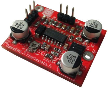 OpenEMG PCB (SMD version).
With its compact form factor, this sensor board outputs an analog voltage (0 to 5 V), depending of the muscular signal.
This video showcases the project:
Features & usage
This table gives the electrical caracteristics of the board.
| Description | Value |
|---|---|
| Input Voltage | 5 V |
| Output Voltage | 0 to 5 V (proportional to muscle contraction) |
| Maximum input current | < 10 mA |
OpenEMG should be wired like this:
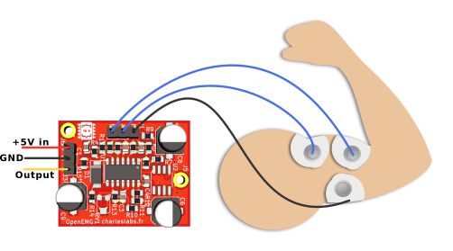 Both muscle electrodes must be placed on the same muscle, about 2 cm apart; the ground electrode should be place on a neutral zone (bone) about 5cm from the other electrodes.
On the board, there is a potentiometer to tune the gain of the output amplifier. This gain is strongly dependent on the muscle that is measured and the position of the electrodes. If it is set too high, OpenEMG will be very sensitive and output either 0 or 5 V. If it is set too low, muscle contractions may not be properly picked up.
This graph shows the analog output value of OpenEMG for a series of muscle contractions (the biceps in this case):
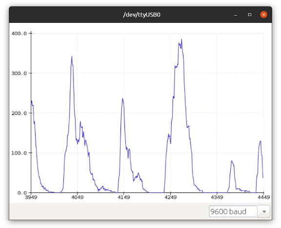 Biceps activity measurements with OpenEMG, viewed in the Arduino serial plotter
For instance, this video shows a basic sketch that turns a servomotor based on the strength of the contraction (old THT version of the board).
The graph in the top right corner displays the output waveform of the board as it is read from the Arduino nano.
The corresponding Arduino code is the following:
#include <Servo.h>
Servo myServo = Servo(2);
void setup(){
    myServo.attach();
}
void loop(){
    myServo.write(map(analogRead(A0),0,1023,0,180));
    delay(50);
}
Principle of operation
OpenEMG's circuit is designed to be as simple to make as possible. This is the complete circuit diagram (click on image to view in full-screen):
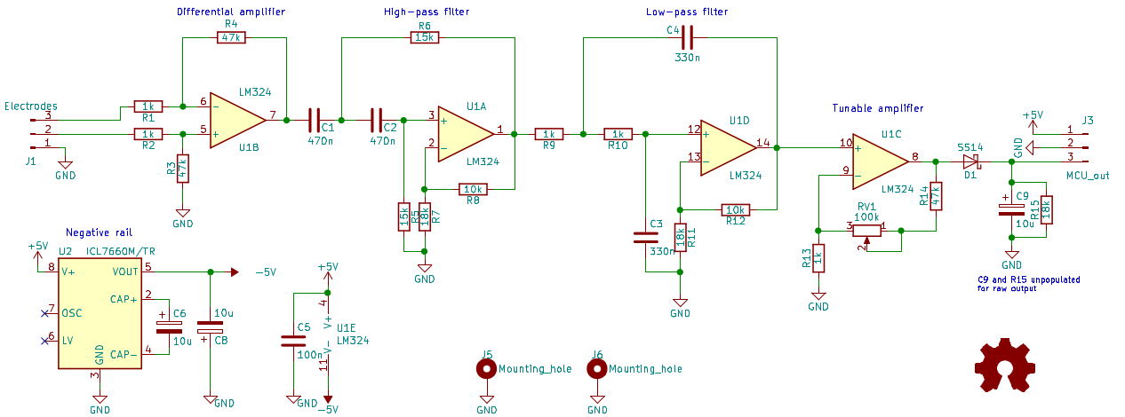
There are 5 parts to this circuit:
- The ICL7660 generates a -5 V rail for the operational amplifiers;
- The first OP-amp (U1B) is a classic differential amplifier configuration;
- The next two OP-amps (U1A and U1D) are a second order band-pass filter with a gain of 2.5 and a frequency range of 20 Hz to 500 Hz;
- The last OP-amp (U1C) is an amplifier with a tunable gain from 50 to 150;
- Finally, D1 rectifies and C9 smooths the signal to make it readable by a micro-controller.
The LM324 chip can be replaced with any pin-compatible quad OP-amp, such as the TL084.
Note: the C9 capacitor makes the output more micro-controller friendly. It can be removed to obtain the raw signal.
Downloads
I designed two versions of the PCB:
- A standard through-hole version;
- A more compact surface mount version.
Both version are functionally identical.
Link to the GitHub repository: https://github.com/CGrassin/OpenEMG
In the release archives, you will find:
- The KiCad circuit design files;
- The bill of material (BOM);
- The Gerber files for manufacturing.
Surface-mount (SMD) version
The surface mount (SMD) version is compact and suitable for professional PCB manufacturing.
It is 32 mm×26 mm, using 0805 components (fairly easy to hand-solder) and single-sided. I ordered panels of it on JLCPCB.
Links to the latest release:
Through-hole (THT) version
As an alternative, the through-hole (THT) version is designed to be very easy to make with DIY tools: it is a single layer board with large clearances and wide tracks.
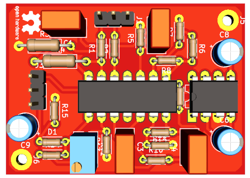
It is 47 mm×35 mm. See my article on homemade PCB manufacturing.
Links to the latest release:
Safety warning: It is recommanded that the power supply of the Arduino is not connected to the wall outlet. Although it is very unlikely, a faulty power adapter could technically have its output connected to the live wire!
Bonus - ECG with OpenEMG
Although OpenEMG is designed for electromyography, I tried placing the electrodes near the heart (positions V3 and V4). I removed the C9 smoothing cap to get the raw capture. This graph is the result:
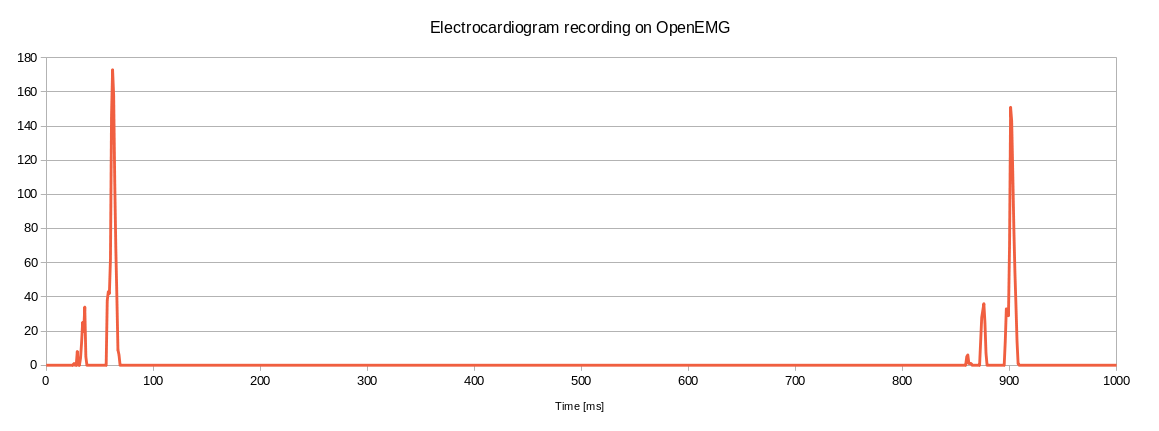
We can clearly see 3 pulses per cycle, separated by 850 ms (70 BPM).
Author: Charles Grassin
What is on your mind?
Sorry, comments are temporarily disabled.
#1 student
on March 16 2019, 18:04
#2 Magansomaa
on August 5 2019, 19:24
#3 Magansoma
on August 5 2019, 19:27
#4 Magansoma
on August 5 2019, 19:30
#5 fanton
on October 5 2019, 18:10
#6 Paul
on October 21 2019, 14:09
#7 Chris
on June 15 2020, 21:38
#8 O.o.o.
on June 17 2020, 10:12
#9 Author Charles
on June 18 2020, 19:35
#10 Author Charles
on June 18 2020, 19:36
#11 Heat_Sink
on July 2 2020, 20:40
#12 arduini
on July 2 2020, 20:42
#13 Ganesh
on July 10 2020, 14:31
#14 Author Charles
on July 11 2020, 7:59
#15 Josh
on July 25 2020, 17:51
#16 Author Charles
on July 27 2020, 11:27
#17 B
on November 10 2020, 15:14
#18 Author Charles
on November 10 2020, 17:28
#19 Vladimir
on March 16 2021, 11:43
#20 Bart
on March 20 2021, 16:24
#21 Author Charles
on March 26 2021, 21:28
#22 Konstantin
on April 15 2021, 9:21
#23 James
on June 8 2021, 12:29
#24 Fredy
on March 21 2022, 3:16
#25 yenni
on September 7 2022, 20:45
#26 Ief
on November 16 2022, 12:35
#27 Apurbo
on January 14 2023, 2:37
#28 Hio
on March 20 2023, 11:07
#29 Sti
on March 20 2023, 21:17
#30 vaso
on May 16 2023, 12:14
#31 Durcau Valentin
on May 25 2023, 11:43
#32 Alex
on September 10 2024, 23:20
#33 Rebecca
on January 7 2025, 21:35