What is BioSignals?
BioSignals is an inexpensive 8-channels bio-sensing acquisition board for Electromyography (EMG), Electrocardiography (ECG), Electroencephalography (EEG), and more. It has a small size of only 5×6 cm and is fully open-hardware.
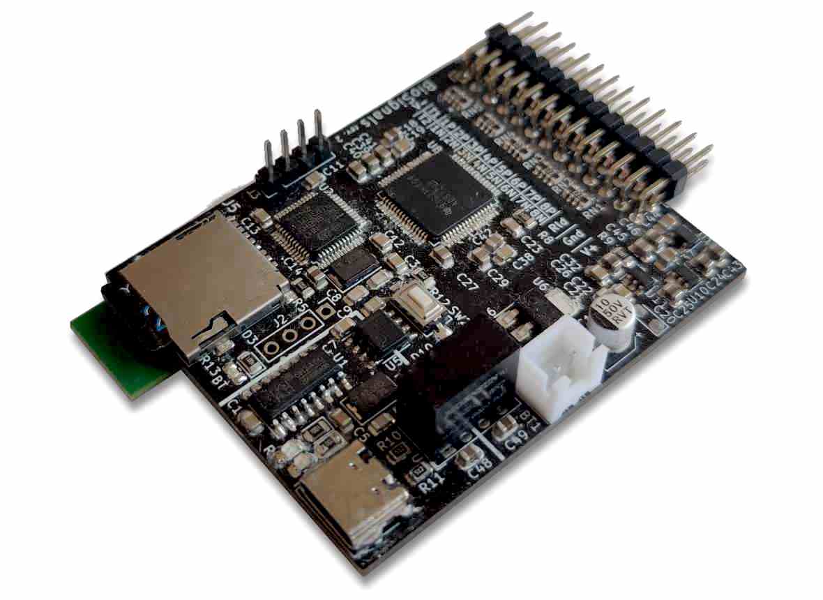 Photo of the assembled BioSignals PCB (rev. 2).
This system is intended for research. Its performance is comparable to medical-grade EEG equipment [1].
The device is powered by batteries or USB and outputs data through galvanically isolated USB, microSD, and/or Bluetooth, making it flexible and adaptable to different settings and equipment.
Features
BioSignals is a highly versatile bio-sensing acquisition board with the following key features:
| Characteristic | Value |
|---|---|
| Analog interfaces * | Up to 8 channels @ 24 bits, PGA (1-24×), 121 dB SNR, up to 32 kSPS Right Leg Drive (RLD) Amplifier, Wilson Center Terminal (WCT) |
| Data interfaces | USB-C (galvanic isolation >4 kV peak) Bluetooth MicroSD |
| Power input | USB-C (galvanic isolation >3 kV peak) Battery (typically 4×AA batteries, 4-12V input) |
| BOM cost * | €25 to €80 depending on the ADC |
| ESD protection | ±15 kV IEC 61000 ESD, EFT and surge protection on all analog channels and USB |
Multiple BioSignals devices can be connected to a single host PC, providing scalability.
(*) The performance metrics listed here depend on the choice of ADC, and different options offer varying levels of performance and cost.
Download and usage
The BioSignals project files, including hardware, firmware, and software, are available for download from the GitHub repository: https://github.com/CGrassin/biosignals.
The next section, "Applications," provides detailed examples of typical use cases for the BioSignals system.
Like many modern Arduino-compatible boards, BioSignal uses the CH340G USB-to-UART transceiver. Installing drivers for this chip might be required on Windows.
Applications
This section goes over the electrode placement techniques and describes typical applications performed with the BioSignals system: EMG, ECG and EEG.
Safety Note: Despite the galvanic isolation, it is highly recommended to operate the system wirelessly on batteries when taking measurements to avoid any risk of surges. Using batteries also eliminates the switching noise of the USB power input.
Note: all the experiments below were performed with a ADS1298 chip (see Electronics section for more details about the performance and characteristics of each compatible chip).
Measurement techniques
There are two ways to use each BioSignals acquisition channel: single-ended input mode or differential input mode.
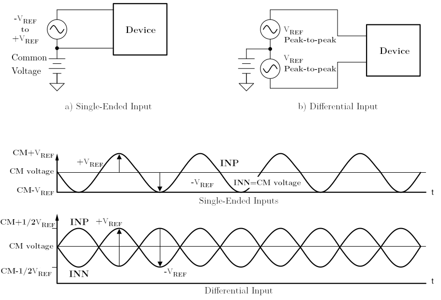 Single-ended and differential input modes illustration from the ADS129x datasheet.
In differential mode, the positive and negative electrode must be placed across the source of bio-potential to be measured (see the EMG example below for instance). Using the differential mode provides the best common-mode rejection (CMR) and delivers better performance. However, it requires two electrodes per channel, which is not practical for some types of measurements like EEG.
In single-ended mode, a common negative electrode is used for several (or all) channels, while each positive electrode is placed on a point to be measured. The way to wire it in practice depends on the family of ADC:
- With the ADS1299, the "SRB2" (Stimulus, Reference and Bias) configuration bit allows to internally connect each channel negative electrode to a common reference input SRB2. This feature is unfortunately not available on the lower-grade ADCs. In addition to the better PGA gain, this makes the ADS1299 a better choice if the target application is EEG.
- For the ADS1294/6/8 and ADS194/6/8 families, each channel negative needs to be externally connected to a single reference electrode, at the cost of more wiring complexity.
The figure below illustrates the wiring for single-ended mode with the ADS1299 ADC:
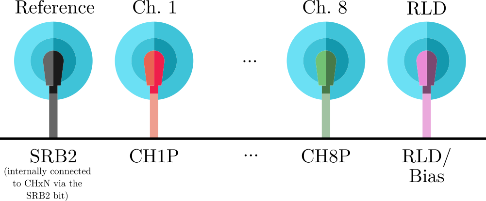 In single-ended measurement with the ADS1299, the SRB2 input can be used as a common reference.
In the ADS1294/6/8 and ADS194/6/8 families, the wiring required for single-ended mode is shown in the following diagram:
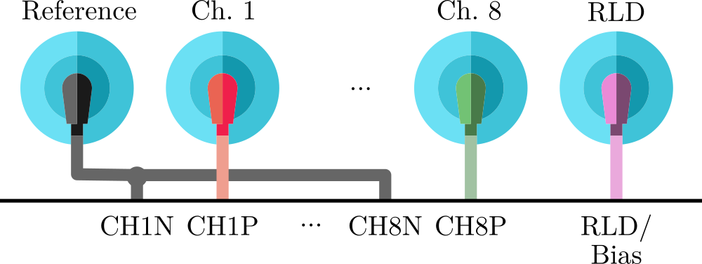 Alternative single-ended measurement wiring using external common electrode.
Note that note all channels don't have to be used in differential or single-ended mode at the same time - both modes may be used simultaneously.
The bias/RLD electrode should be placed on a neutral zone to improve the signal-to-noise ratio (see examples below).
Electromyography (EMG)
Electromyography is a technique used to record the electrical activity of muscle tissue. It is one of the most basic applications of BioSignals.
To perform EMG, a single pair of differential electrodes is placed across the muscle, with a third RLD electrode on a neutral zone (bone) to reduce noise. The electrode placement is shown in the picture below:
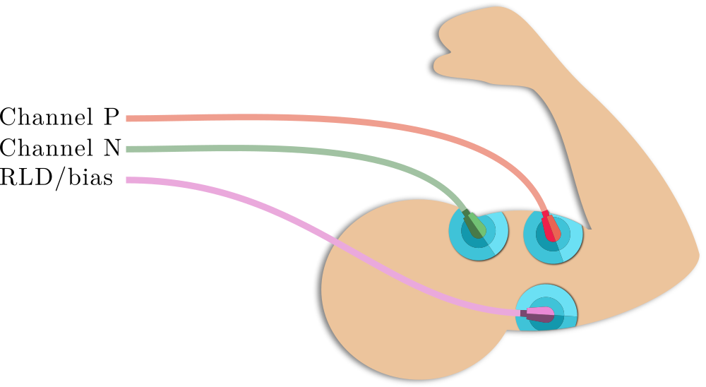 Typical electrode placement for EMG.
Note: the RLD electrode reduces the noise but it is not strictly required.
This is a typical measurement of a series of bicep contractions:
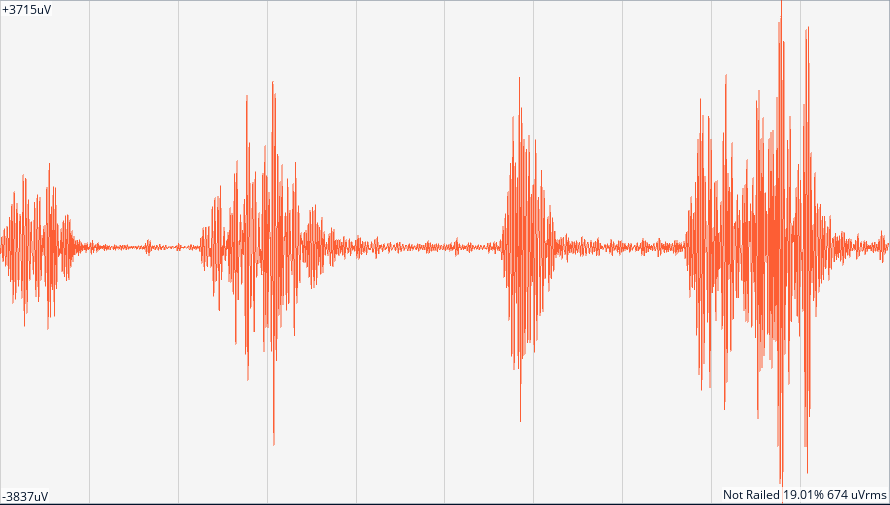 Plot of a recording of the electrical activity of the bicep captured by BioSignals.
The amplitude of the EMG signal is proportional to the intensity of the muscle contraction. The envelope of this signal can be used to control prosthetic limbs, among other things.
The signal processing applied for the application may use the default OpenBCI GUI settings. In this case:
- 50 Hz notch filter to remove the mains common noise,
- Channel PGA at 4×, default sampling rate (250 SPS),
- 4th order bandpass filter (5 Hz to 60 Hz).
More complex measurements can be performed using multiple electrode pairs on multiple muscle groups or by using single-ended measurements on multiple muscles of a muscle group.
Electrocardiography (ECG/EKG)
Electrocardiography is the measurement of electrical activity in the heart.
The following measurement is performed with a single differential electrode pair across the heart in positions V2 of the 12-lead ECG placement standard (fourth intercostal space at the left border of the sternum) and V4 (fifth intercostal space at the midclavicular line). A reference (RLD) electrode is placed on the manubrium bone to improve the signal.
The diagram hereunder illustrates this electrode placement:
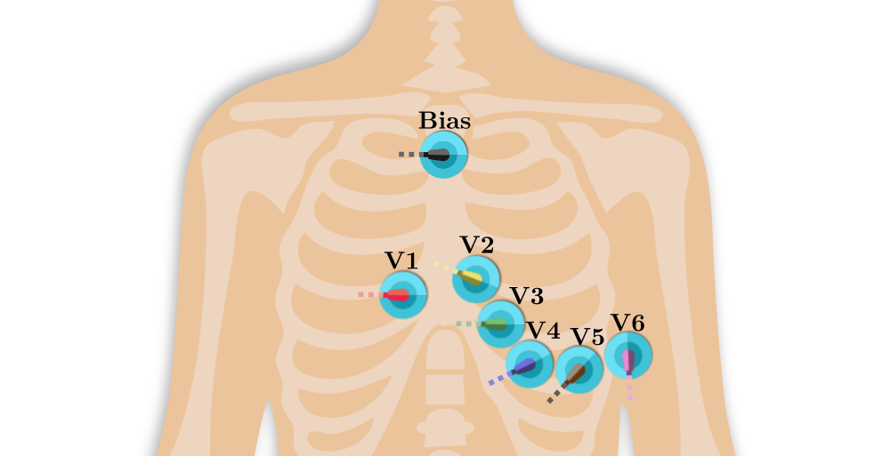 Typical electrode placement for ECG (from the 12-lead ECG system).
This is a snapshot from a live measurement in this configuration:
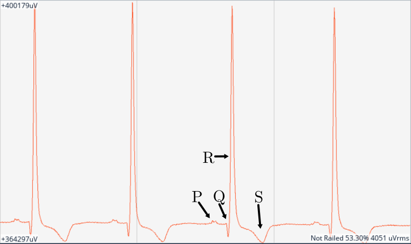 Recording of an ECG measurement. The P, Q, R and S waves can clearly be seen.
The signal processing applied on this example uses the following settings:
- Channel PGA at 6×, default sampling rate (250 SPS),
- No filtering.
This clip shows a live recording of this data visualized in OpenBCI GUI:
Data-stream of ECG data visualized in OpenBCI GUI.
ECG measurements can be augmented by using single-ended mode to independently measure each point.
Electroencephalography (EEG)
Electroencephalography is the measurement of electrical activity in different parts of the brain. EEG is one of the more advanced applications of BioSignals as the signals are very low amplitude, which worsens the signal-to-noise ratio (SNR).
For EEG measurements, one ear-clip electrode should be used for the bias/RLD (LPA), another one for the negative reference (RPA), and the single-ended positive electrodes can be placed on the skull, following the standard international 10–10 or 20-10 system:
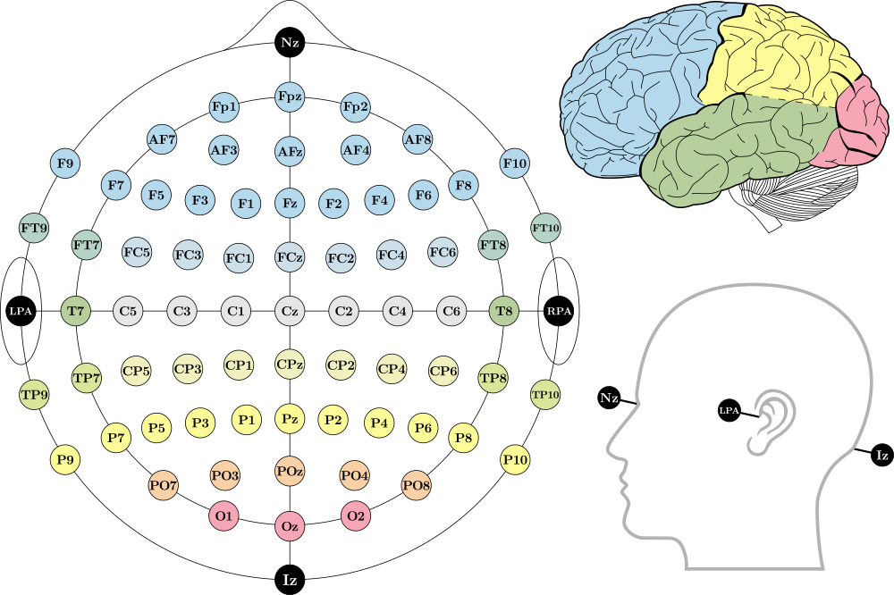 EEG electrode positions in the 10-10 system, by Laurens R. Krol - Own work, CC0, on Wikimedia.
To measure these positions, an EEG headset is required. The Ultracortex is an open-source, 3D-printable head-wear for EEG. I designed a simplified version for much easier printability, which uses spring-mounted passive dry Ag/AgCl electrodes that contact the scalp through the hair.
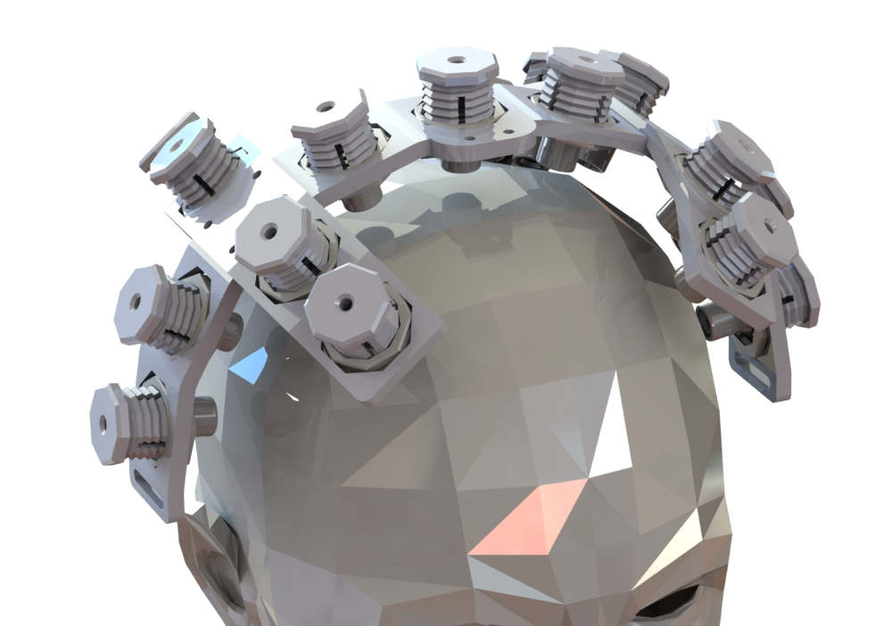 Render of the 3D printable EEG headset.
The screenshot below shows a two-channel EEG recording captured by BioSignals. Channel 1 (grey) is positioned on location C3, and channel 2 (purple) on C4.
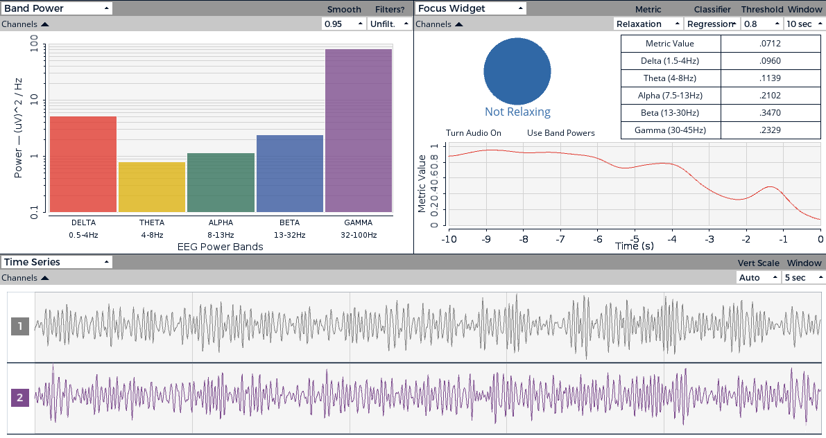 Plot of a two-channel EEG recording captured by BioSignals.
EEG signals typically appear rather noisy. The interesting metrics are the amplitude of each channel vs time and their frequency components. The OpenBCI GUI displays the power band for each brain wave type (Delta, Theta, Alpha, Beta, and Gamma) and provides several ways to visualize and analyze this data, such as the "Focus Widget" or the "Head plot".
Design
The BioSignals system's design is based on the following architecture diagram:
 Top-level architecture diagram of the BioSignals system.
This section summarizes the electronics, firmware and software design.
Electronics
The electronics design is based on an STM32 (STM32F103C8T6), a 32-bit ARM Cortex M3 running at 72 MHz. This provides sufficient computational power headroom, in case on-board processing is required, such as digital filtering or packet compression.
The primary design driver of the system is the delta-sigma (ΔΣ) analog-to-digital converters (ADC). The ADS1x9x series of analog front-ends for bio-potential measurements developed by Texas Instruments are ideal for this application. The BioSignals PCB can support all pin-compatible TQFP-64 chips in this series, depending on the desired price/performance ratio and intended application.
The table below summarizes their capabilities:
| Device | Channels | Max. Gain | Resolution | Max. sample rate | Approx. unit price |
|---|---|---|---|---|---|
| ADS1194 | 4 | 12 | 16 bits | 8 kSPS | €13 |
| ADS1196 | 6 | 12 | 16 bits | 8 kSPS | €15 |
| ADS1198 | 8 | 12 | 16 bits | 8 kSPS | €20 |
| ADS1294 | 4 | 12 | 24 bits | 32 kSPS | €24 |
| ADS1296 | 6 | 12 | 24 bits | 32 kSPS | €32 |
| ADS1298 | 8 | 12 | 24 bits | 32 kSPS | €38 |
| ADS1299-4 | 4 | 24 | 24 bits | 16 kSPS | €38 |
| ADS1299-6 | 6 | 24 | 24 bits | 16 kSPS | €50 |
| ADS1299 | 8 | 24 | 24 bits | 16 kSPS | €64 |
The recommended ICs are:
- The ADS1198/6/4 series is suitable for measuring strong signals like ECG or EMG while keeping the BOM cost low.
- The ADS1299 series offers the best performance and is recommended for precision measurements like EEG.
- The ADS1298/6/4 series is a cost-effective alternative to the ADS1299 and can be used for the same applications (including EEG), albeit with slightly worse performance.
The baseline is the ADS1299.
The PCB is routed on only two layers. It uses 0805 passives in order to be easy to be easy to hand-assemble.
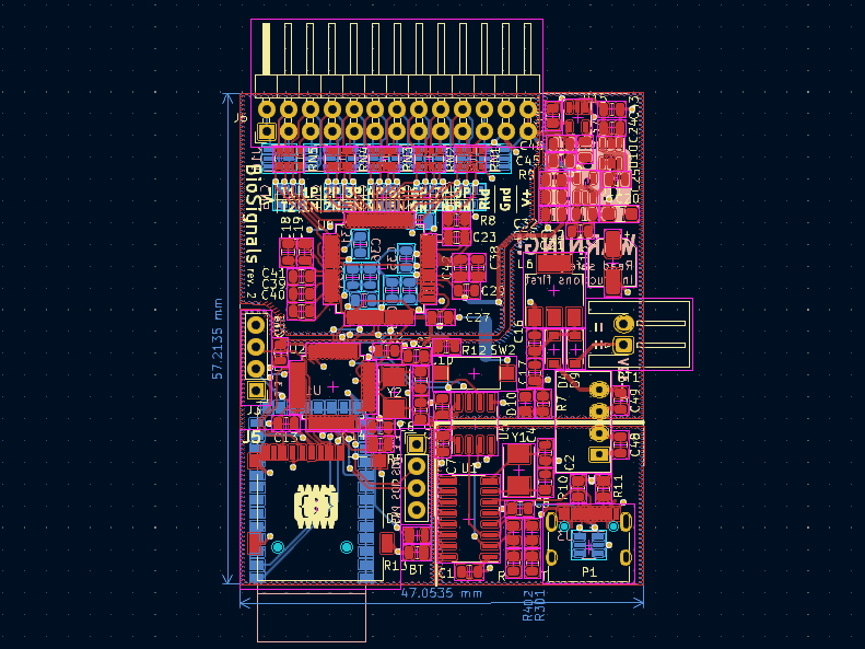 The PCB file in the KiCad PCB editor.
The analog channel input pins feature an RC low-pass anti-aliasing filter (cut-off frequency of 72 kHz) and ESD protection.
The USB section is fully galvanically isolated from the rest of the circuit. The 5V DC power rail is isolated with an integrated DC-DC converter. The data interface uses a USB-to-serial converter that is isolated with a silicon-dioxide isolation barrier IC.
Several power supply rails are required: 3.3 V for the digital devices, positive 2.5 V and negative 2.5 V for the ADC analog rails. It uses star grounding to improve the analog performance.
The Bluetooth functionality is implemented with a HC-06 module.
A spare I2C connector is included. It is intended to provide an interface to wire external sensors such as temperature sensors, accelerometers, GPIO expander, etc. This function is not supported by the OpenBCI interface.
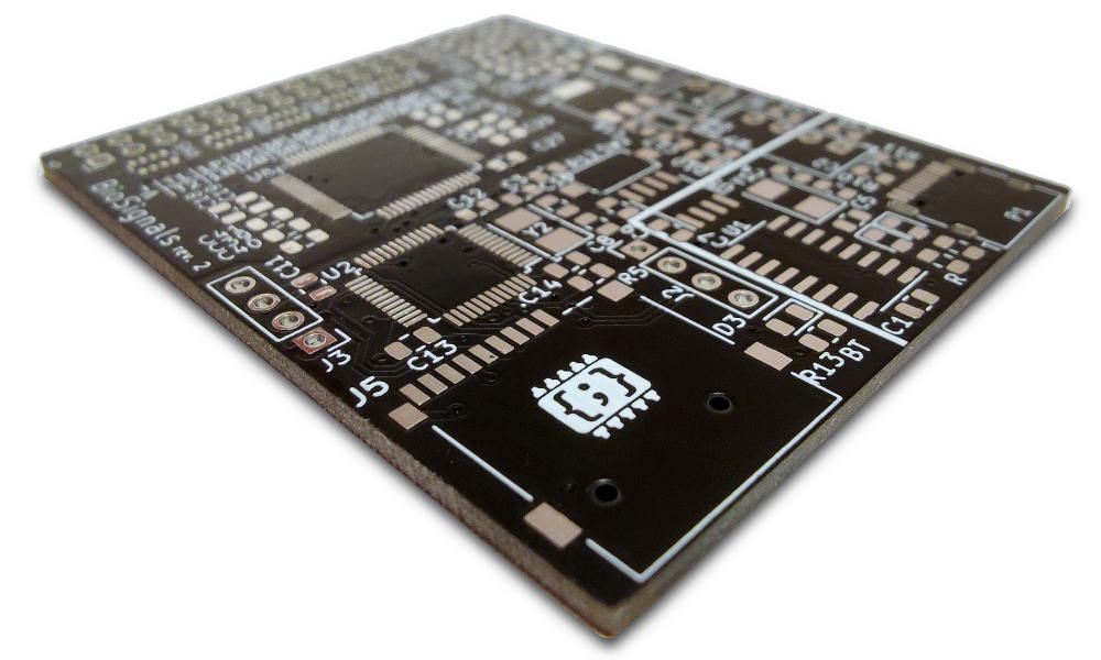 Photo of the bare BioSignals PCB without components (rev. 2).
Firmware
The firmware running on the STM32 microcontroller is responsible for receiving commands, configuring the ADC accordingly, and outputting data to the peripherals as requested. The current version of the firmware only performs minimal on-board processing of the data, limited to optional down-sampling.
To ensure compatibility with all software developed for OpenBCI, the command and data packets interface was implemented following OpenBCI's Cyton interface specification. Some additional commands were added, such as a lower minimum sample rate. The interface is fully documented in the GitHub repository.
The firmware is compatible with all three families of ADS front-ends, despite their slightly incompatible SPI interface. The target chip to be supported by the STM32 is determined at compile time.
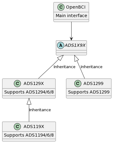 C++ class diagram of the firmware.
The OpenBCI interface has some limitations on the capability of the device, such as the inability to use and configure the WCT feature of the ADS129x chips. To access the full feature set of these devices, the ADS C++ classes provide an abstraction layer, which requires additional development time to design a custom interface and software. However, all of the low-level communication protocol and configuration are already implemented.
To program the firmware on the STM32, an ST-Link programmer/debugger is used on the SWD connector. This is a one-time requirement.
Software
BioSignals is compatible with all software developed for the OpenBCI platform, thanks to its implementation of the OpenBCI interface. This includes the OpenBCI GUI, a Processing application that can be used to control the hardware, visualize physiological data, and stream it to other applications and tools.
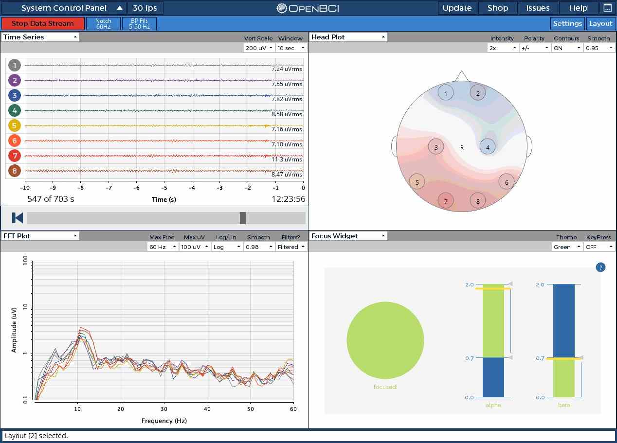 The user interface for OpenBCI GUI.
Data can be displayed in live-time, played back as well as saved to the computer in .txt format. The data can also be streamed to third-party software through the open-source Brainflow library:
- Python, Java, R, Julia, C++, Rust, Matlab and C# with Brainflow API language bindings
- Neuromore
- OpenViBE
- LSL
- BrainBay
- BioEra
Details on how to use the software with BioSignals, along with example projects, are available in the OpenBCI documentation: https://docs.openbci.com/
Conclusion and future improvements
The BioSignals device provides a low-cost and versatile platform for acquiring bio-potentials, such as EEG, ECG, and EMG. Its compact and portable design makes it suitable for a wide range of research applications, even outside of the biology field. The device is built around the STM32 microcontroller and features a flexible firmware that supports multiple families of ADS front-ends. Its compatibility with the OpenBCI interface and software ecosystem allows for easy integration with a variety of third-party tools and applications.
Moving forward, several improvements are planned for the revision 3 of the board. These include adding a jumper or switch to disable the 5V USB power while keeping the serial data IO, switching to 4-layer manufacturing to improve power distribution, adding a daisy chaining connector and designing an expansion module to support up to 32 channels, and adding mechanical mounting holes to the board.
Links
- Jérémy Frey. Comparison of a consumer grade EEG amplifier with medical grade equipment in BCI applications. International BCI meeting, May 2016, Asilomar, United States. hal-01278245 ↩
- OpenBCI documentation: https://docs.openbci.com/
- BioSignals GitHub repository: https://github.com/CGrassin/biosignals
Author: Charles Grassin
What is on your mind?
Sorry, comments are temporarily disabled.
No comment yet!