Note: This is an early version of the project. I plan to update some of the blocks while maintaining full compatibility with the current design. More specifically, the next step is to do a major redesign to replace all the screws with solid snap-fits.
What are Shablocks?
An Arduino board and a few basic components are often the only requirements to start tinkering with electronics, robotics, etc. However, when going a step further and setting up an electronic lab with test equipement (an oscilloscope, a variable power supply, etc.), the costs and cumbersomeness quickly grow.
Shablocks is a project to make an elegant solution for an inexpensive, modular, evolutive and complete electronic lab. It uses popular modules and kits from China in a convenient format.
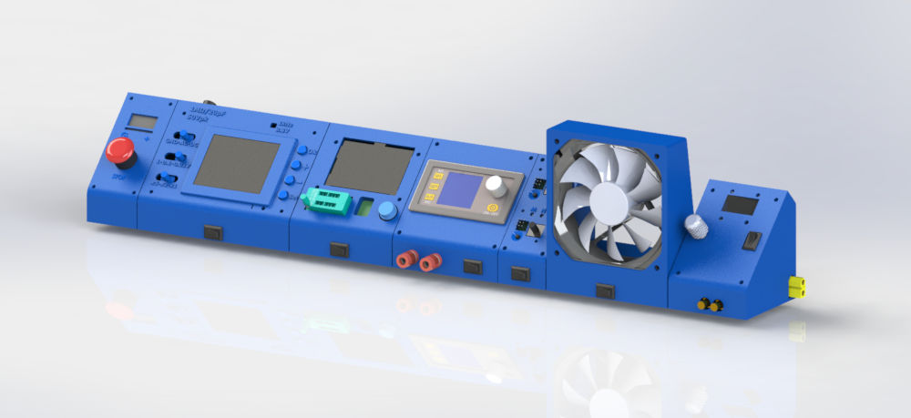 An exemple Shablock setup
With its compact size, you can take it on the go and power it from a laptop power brick or a 4-6s lipo battery!
Getting started (prerequisites)
To get started with Shablocks, you only need a laptop power supply (or any power supply than ouptuts between 12 V and 24 V DC). You also need to make the DC power input adapter: a DC barrel plug to XT60 female connector.
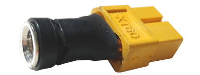
With this power supply and adapter, you are ready to go!
The modules
By design, all the modules are independant. Build those you need, and expand as you do more projects! For each module, you will find an overview of the features, a quick guide on how to build them and the parts/costs list.
To build the modules, you only need a 3D printer and a soldering iron.
This is the current list of modules:
- Digital power supply
- Component tester
- Oscilloscope
- Servo tester
- Input protection
- Soldering smoke extractor
- TS100 power cable
Click on this button to download the archive containing all the Shablocks (STL 3D-printable files):
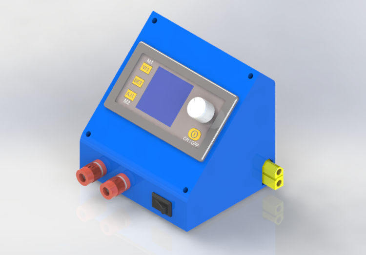
Digital power supply
A variable power supply is the center element of any electronics lab. It is essential to safely power any project. The "DPS" power supply series from RD tech are the most popular DIY digital power module for a reason: they are very practical, with a clear interface to set and display the current, voltage, power, etc. It outputs 0 V to 30 V (capped by the power input) and up to 3 A.
Parts list
- 4×M3 screw
- A DSP3003 module ($20)
- 2×banana 4 mm plugs ($0.50)
- A 10×15 mm rocker switch ($0.10)
- XT60 male+female plugs ($0.30)
Build instructions
Simply print the body and the lid, and wire the module as shown under.
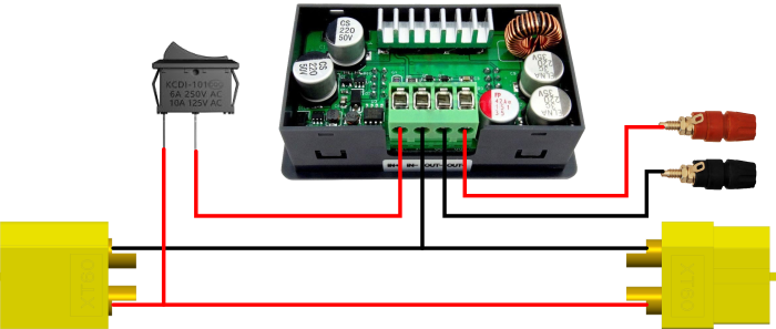 The Digital power supply module wiring diagram.
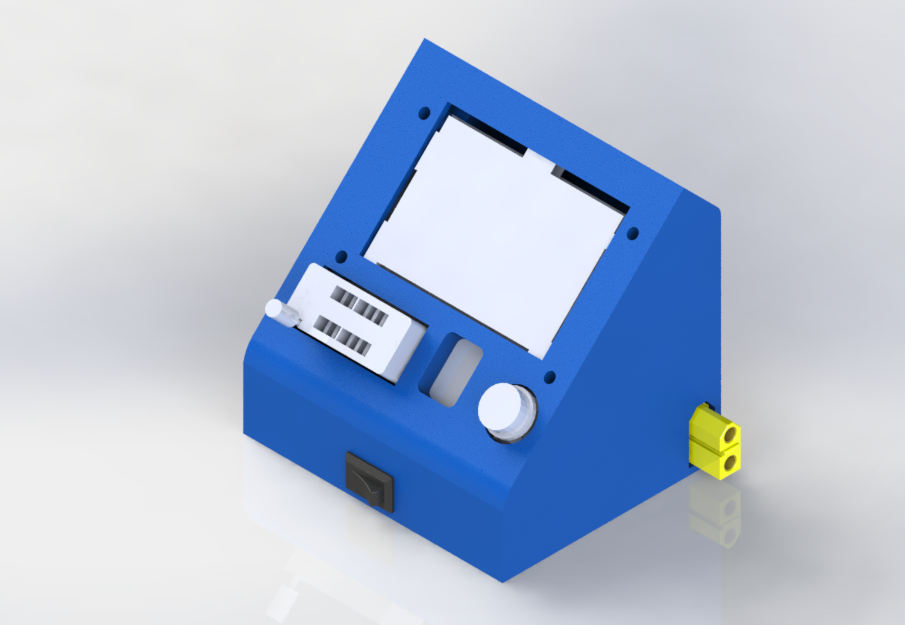
Component tester (LCR-T4)
This components tester can automatically detect and measure NPN and PNP transistors, N-channel and P-channel MOSFETs, diodes, thyristors, resistors, capacitors and more parts. It shows valuable information: value, gain, ESR, forward voltage, gate capacitance, etc. Although not strictly necessary, it is a surprisingly handy tool to have.
Parts list
- 4×M3 screw
- A LCR-T4 component tester board ($6.50)
- Mini360 power module ($0.30)
- A 10×15 mm rocker switch ($0.10)
- XT60 male+female plugs ($0.30)
Build instructions
This is the wiring diagram:
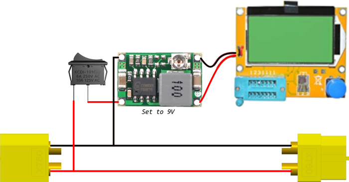 The component tester module wiring diagram.
The input voltage of the LCR-T4 tester is 9 V. Hence, we use a "mini 360" step down converter. It must be trimmed before soldering everything together!
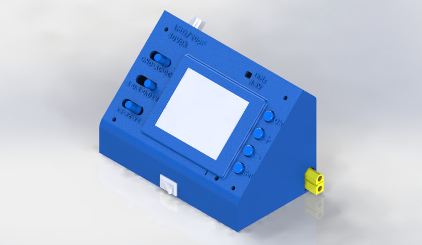
Oscilloscope (DSO138)
This tiny oscilloscope scope has limited bandwidth (100 kHz), sample rate (1 MSps) and features. However, it will definitely come handy for low frequency analog work & general quick debug. In fact, it is one of the must-haves of this system! You can either buy the DSO138 as a kit or fully soldered.
Parts list
- 4×M3 screw
- A DSO138 kit ($14.00)
- Mini360 power module ($0.30)
- A 10×15 mm rocker switch ($0.10)
- XT60 male+female plugs ($0.30)
Build instructions
This is the wiring diagram:
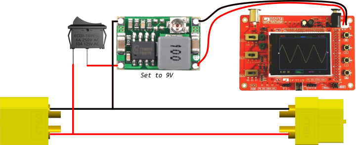 The oscilloscope module wiring diagram.
The input voltage of the DSO138 is 9 V. Hence, we use a "mini 360" step down converter. It must be trimmed before soldering everything together!
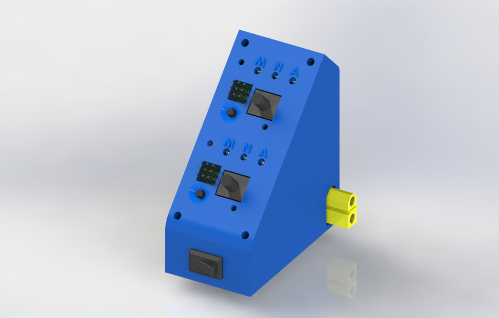
Servo tester
A servo tester is a device that can control servo motors to make sure that they are functioning properly, manually testing mechanisms, controlling ESCs, check consistency, etc. This module contains 2 servo testers, meaning that it can independently control two groups of up to 3 servomotors without having to worry about the wiring to power them. It is very useful for RC and robotics for instance.
Parts list
- 4×M3 screw
- 4×M2.5 screw and nuts
- 2×Servo tester PCB (2×$1.20)
- 2×Mini360 power module (2×$0.30)
- A 10×15 mm rocker switch ($0.10)
- XT60 male+female plugs ($0.30)
Build instructions
This is the wiring diagram:
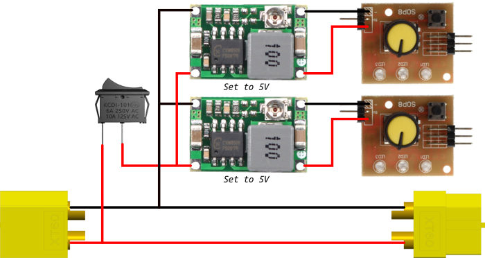 The servo tester module wiring diagram.
The servo tester usually comes with right-angled pins. You must unsolder these and put normal pin header instead. The input voltage of the servo testers is 5 V. Hence, we use a "mini 360" step down converter. It must be trimmed before soldering everything together!
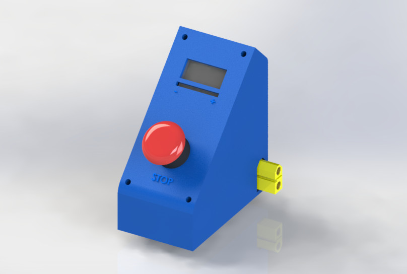
Input protection and safety
This module should be in the right-most position, because it contains two safety mechanisms for the power input of the Shablocks: a emergency cut-off switch and a battery monitor. The emergency switch can instantly cuts the input power while the LiPo/LiFe/Li-ion monitor checks that any the cells do not overcharge/overdischarge.
Parts list
- 4×M3 screw
- 16 mm emergency switch ($1.50)
- Battery monitor/low voltage alarm ($1.20)
- XT60 male+female plugs ($0.30)
Build instructions
The battery tester usually comes with right-angled pins. You must unsolder these and put normal pin header instead.
This is the wiring diagram:
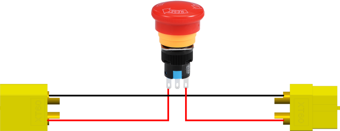 The input module wiring diagram.
Note that, the button is in series with the supply, and that the battery monitor is not connected to anything.
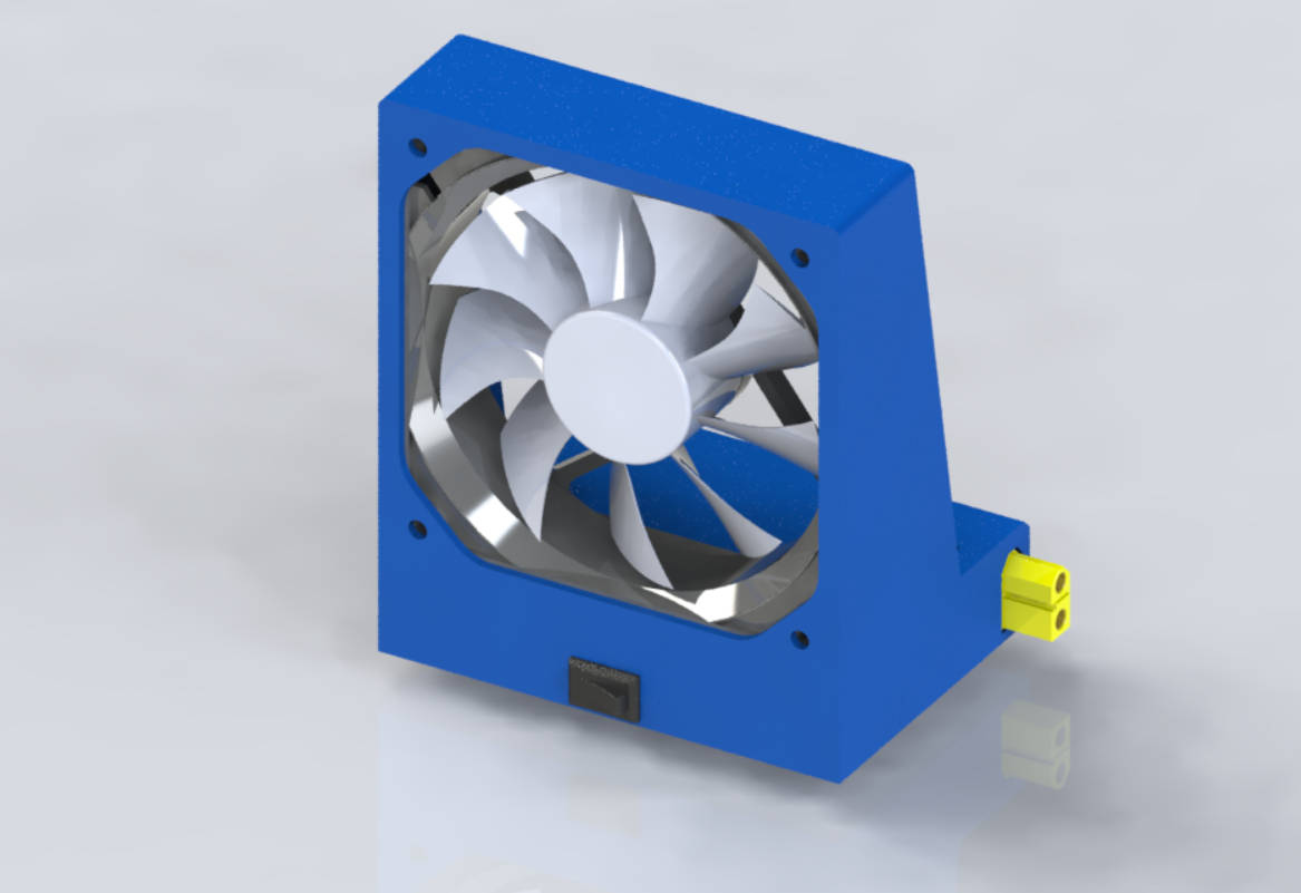
Soldering smoke extractor
Soldering creates lots of unhealthy smoke due to the flux contained inside the tin. This fan prevents the smoke of the solder to directly reach your lungs.
Parts list
- 4×M3 screw
- 4×M4 screw
- A 120 mm computer fan (from $4, but better quality are often quieter)
- A Mini360 power module ($0.30)
- A 10×15 mm rocker switch ($0.10)
- XT60 male+female plugs ($0.30)
Build instructions
The fan should be physically oriented to suck the smoke.
This is the wiring diagram:
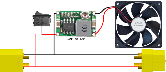 The fan module wiring diagram.
The input voltage of the fan is 12 V. Hence, we use a "mini 360" step down converter. It must be trimmed before soldering everything together! You can trim the voltage lower than 12 V to get less noise. Of course, the airflow is also lowered.
TS100 supply cable
The TS100 is a hugely popular digital soldering iron that I strongly recommend. With this simple cable, you can power it directly from the right side of the lab. This cable is very flexible and heat-resistant, which makes soldering with this a pleasure!
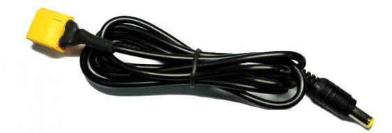
It can be bought for around $3.
General 3D-printing guidelines
I printed all the modules on my Anet A8. I used the following parameters:
| Parameter | Value |
|---|---|
| Material | PLA (from ICE Filaments) |
| Layer height | 0.2 mm |
| Support | No (with exceptions) |
| Shell/wall thickness | 1 mm |
A module usually takes 4 hours of print-time on average. The limiting factor for the print speed is the XT60 clips that must be accurate enough to get a perfect press-fit.
More modules to come!
The objective of this project is to make the most complete solution possible. Hence, there are many more modules I want to design to expand my lab.
This is a list of modules I am currently thinking about adding to the available set:
- [Work in Progress] A USB QC3 module to power USB gadgets such as LED lights or the TS80 soldering iron,
- [Work in Progress] A simple signal generator for low frequency analog work,
- A basic multimeter,
- A computer module based on a Raspberry Pi with a touch screen to code or use a logic analyzer, for example,
- Much more: frequency counter, decade resistor/capacitor box, electronic load...
You can submit your ideas in the comments below!
Auteur : Charles Grassin
What is on your mind?
Sorry, comments are temporarily disabled.
#1 sagan
on September 30 2019, 13:42