Introduction
In RF communications, circular polarization allows a wave to maintain a constant magnitude while its electric field vector rotates, making reception largely independent of the receiving antenna's orientation. One way to achieve this with simple antennas is to arrange orthogonal linear elements and drive them with signals that are sequentially 90° phase-shifted, producing a left-hand or right-hand polarized (LHCP/RHCP) wave depending on the phase sequence. This requires a feed network with equal-amplitude outputs at 0°, 90°, 180°, and 270° phase offsets.
One such application is a CubeSat carrying four orthogonal whip antennas for UHF communications, where the additional constraint is that the network must fit within a very limited volume.
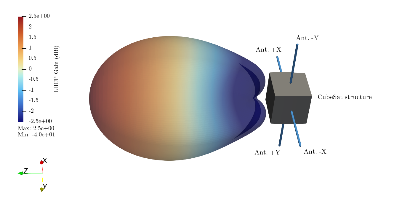 Figure 1: LHCP radiation pattern of an orthogonal four-antenna (-X, +X, -Y, +Y) whip 1U CubeSat configuration fed with quadrature phase (OpenEMS simulation at 435 MHz).
This project develops a compact RF feed network for the UHF band (330–580 MHz, with a focus on 435 MHz for the amateur radio band) using discrete lumped components. The design is a 33×33 mm four-way sequential phase splitter using no magnetics, with good phase/amplitude balance and low insertion loss.
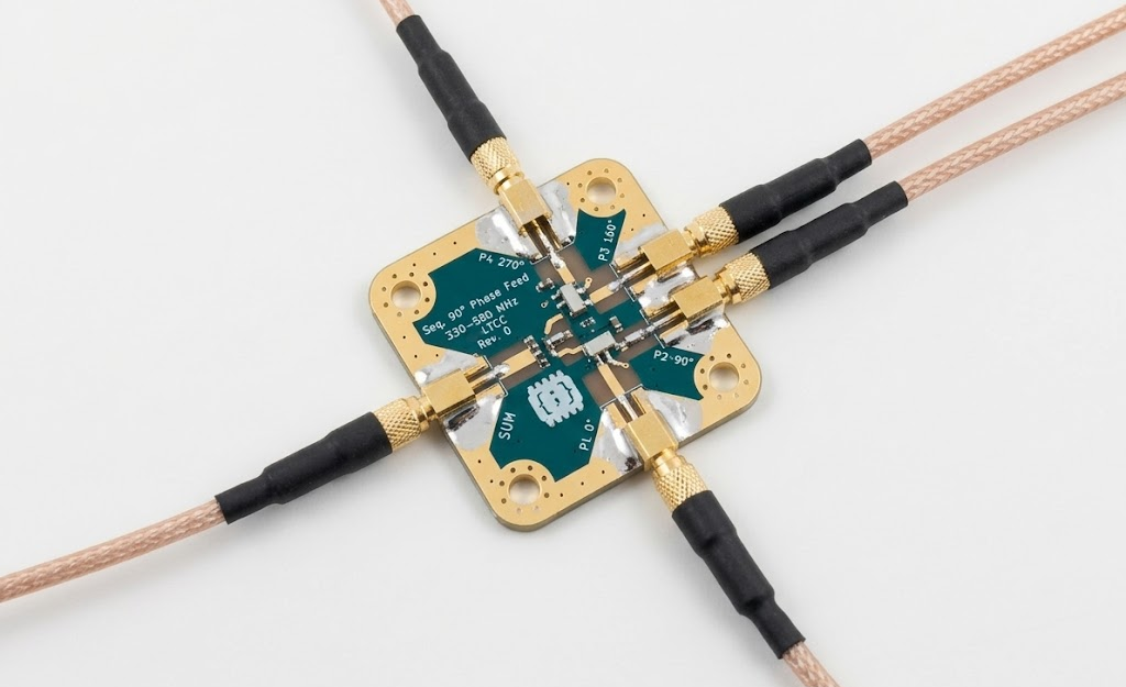 Figure 2: Realized PCB rev. 0 of the quadrature feed network (dimensions: 33×33 mm).
This article presents the performance, the RF architecture and simulation, the realized hardware, and the measurements.
Performance
The following values are the measured performance of the assembled PCB:
| Parameter | 425–450 MHz (BW) | @ 435 MHz |
|---|---|---|
| Phase imbalance | < 3.00° | < 2.79° |
| Amplitude imbalance | < 0.64 dB | < 0.20 dB |
| Insertion loss (in addition to -6 dB, worst port) | −0.78 dB | −0.55 dB |
| Input return loss (worst port) | > 17.5 dB | > 18 dB |
| Maximum input power | > 33 dBm (2 W) | --- |
| Max. input DC voltage | 50 V | --- |
The center frequency can be tuned in the 220 MHz to 1.2 GHz range by adjusting the values of the inductors and capacitors as well as the hybrid (see next section). In the scope of this project, only 330 MHz to 580 MHz with the QCN-5+ hybrid was tested.
Amplitude and phase balance are critical for a high-quality axial ratio, which measures the deviation from perfect circular polarization. Imbalances shift the polarization from circular to elliptical, causing losses. The simulations below compare an ideal feed against specific hardware errors (10° phase and 1 dB amplitude imbalance) using an OpenEMS model of a 1U CubeSat with four whip antennas (see Figure 1).
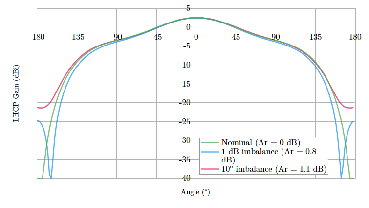 Figure 3: LHCP gain at 435 MHz. The plot demonstrates the pattern sensitivity to feed imbalances in the intended CubeSat application.
An axial ratio of 0 dB represents a perfect circle. We aim to stay below the 3 dB threshold; exceeding this causes significant polarization mismatch loss.
The antenna RF simulation model is included in the GitHub repository.
Network design
The network consists of a cascaded architecture with a 180° power splitter followed by two 90° quadrature hybrids.
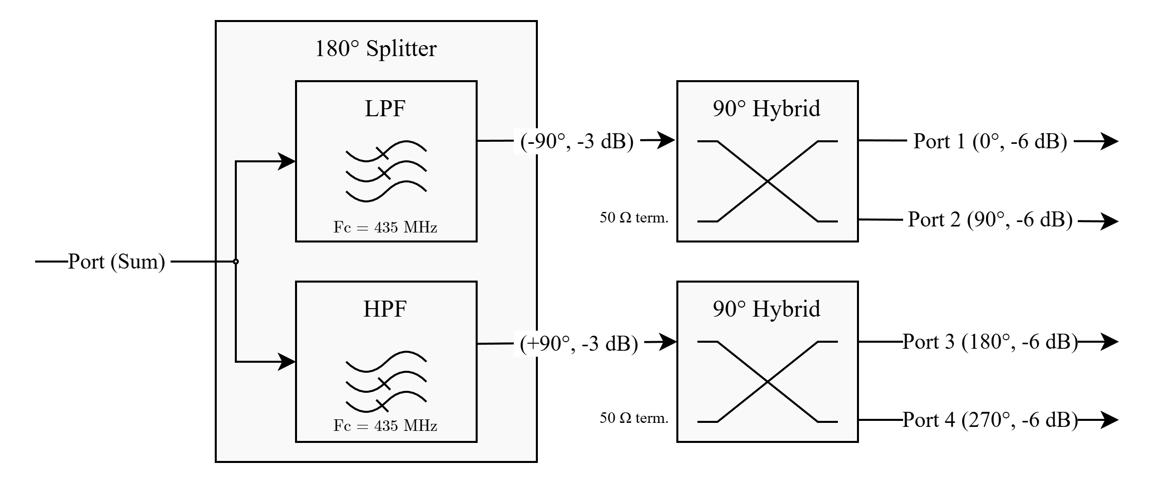 Figure 4: Architecture of the quadrature feed network.
The implementation is:
- 180° Splitter: Lumped LC balun made of a low-pass filter and a high-pass filter fed from the same node. The inductance and capacitance are calculated so that the cutoff frequency of both filters is the target center frequency.
- Quadrature Hybrids (90°): Mini-Circuits QCN-x+ series 2-way 90° power splitter/combiner, LTCC technology, low insertion loss.
The hybrid can be selected in the Mini-Circuits' QCN-x series to choose the operating range of the circuit. Parts are available from 220 MHz to 4.5 GHz, but the upper limit of this circuit is about 1.2 GHz; the LC filters become impractical at higher frequencies.
| Model Number | F Low (MHz) | F High (MHz) |
|---|---|---|
| QCN-3+ | 220 | 470 |
| QCN-5+ | 330 | 580 |
| QCN-7+ | 425 | 675 |
| QCN-8+ | 450 | 750 |
| QCN-12+ | 800 | 1375 |
In the scope of this project, QCN-5+ was selected (330 to 580 MHz bandwidth) for the desired 435 MHz center frequency.
S-parameter simulation
An S-parameter simulation was performed in uSimmics (formerly QUCS-Studio) using manufacturer-provided models. The simulations verified:
- Equal power division across the four outputs
- Sequential 90° phase progression
- Acceptable impedance matching across the intended band
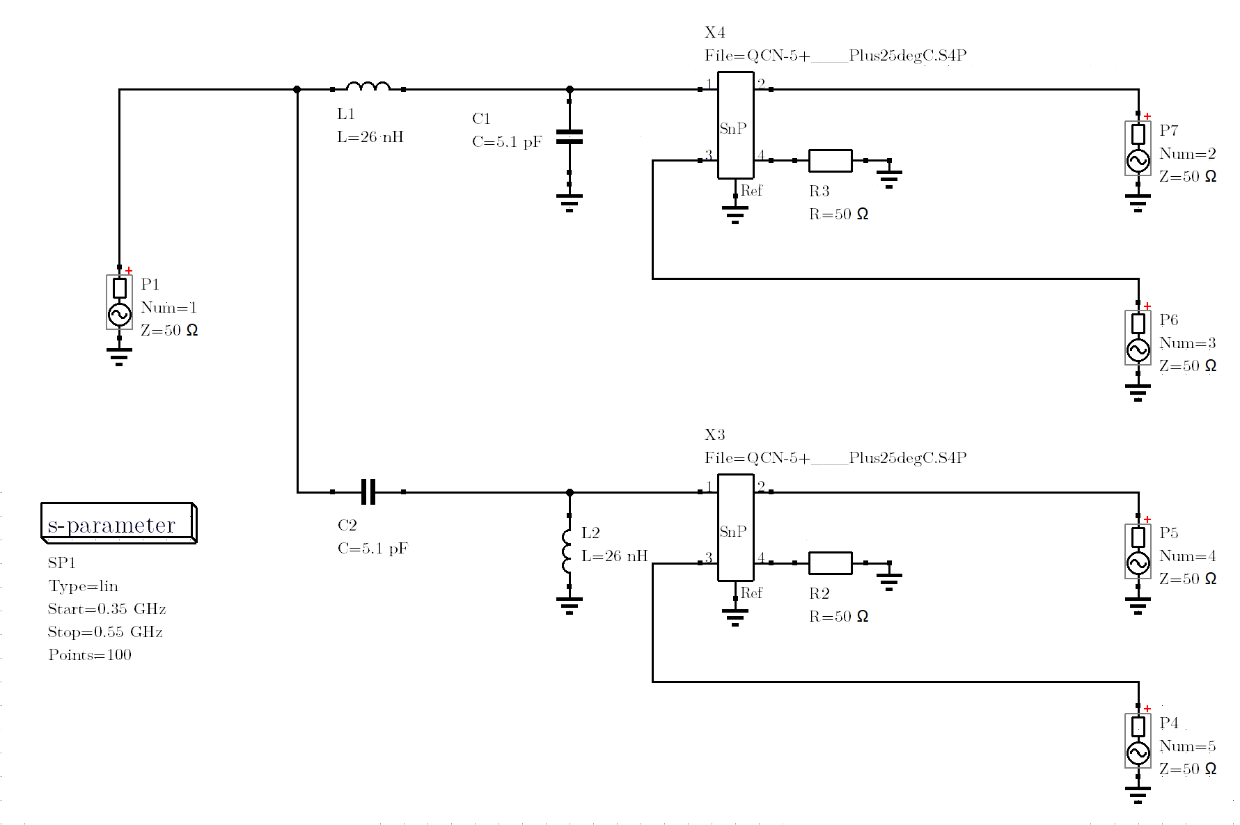 Figure 5: Simulation model of the circuit.
The plots hereunder show the simulation results: the phase deltas (which should be 90°, 180° and 270°), the insertion loss and the return loss for each port.
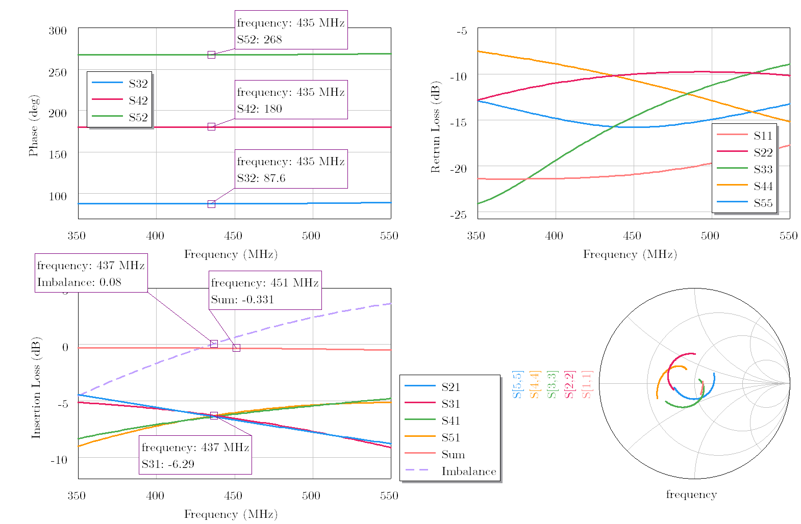 Figure 6: Simulation results, showing the phase relationship, the insertion loss, and the return loss for each port.
This simulation model allows the values of the inductors and capacitors to be tuned to optimize performance over the desired bandwidth of operation.
PCB design and assembly
The PCB was designed in KiCad using common RF design practices. The output traces after the final hybrids were length-matched to minimize phase skew.
The geometry of the LC filters is critical for the RF performance of the circuit: they are fed from the same physical location at the end of a 50 Ω transmission line, routed to minimize parasitic inductance and capacitance, and share their grounding point.
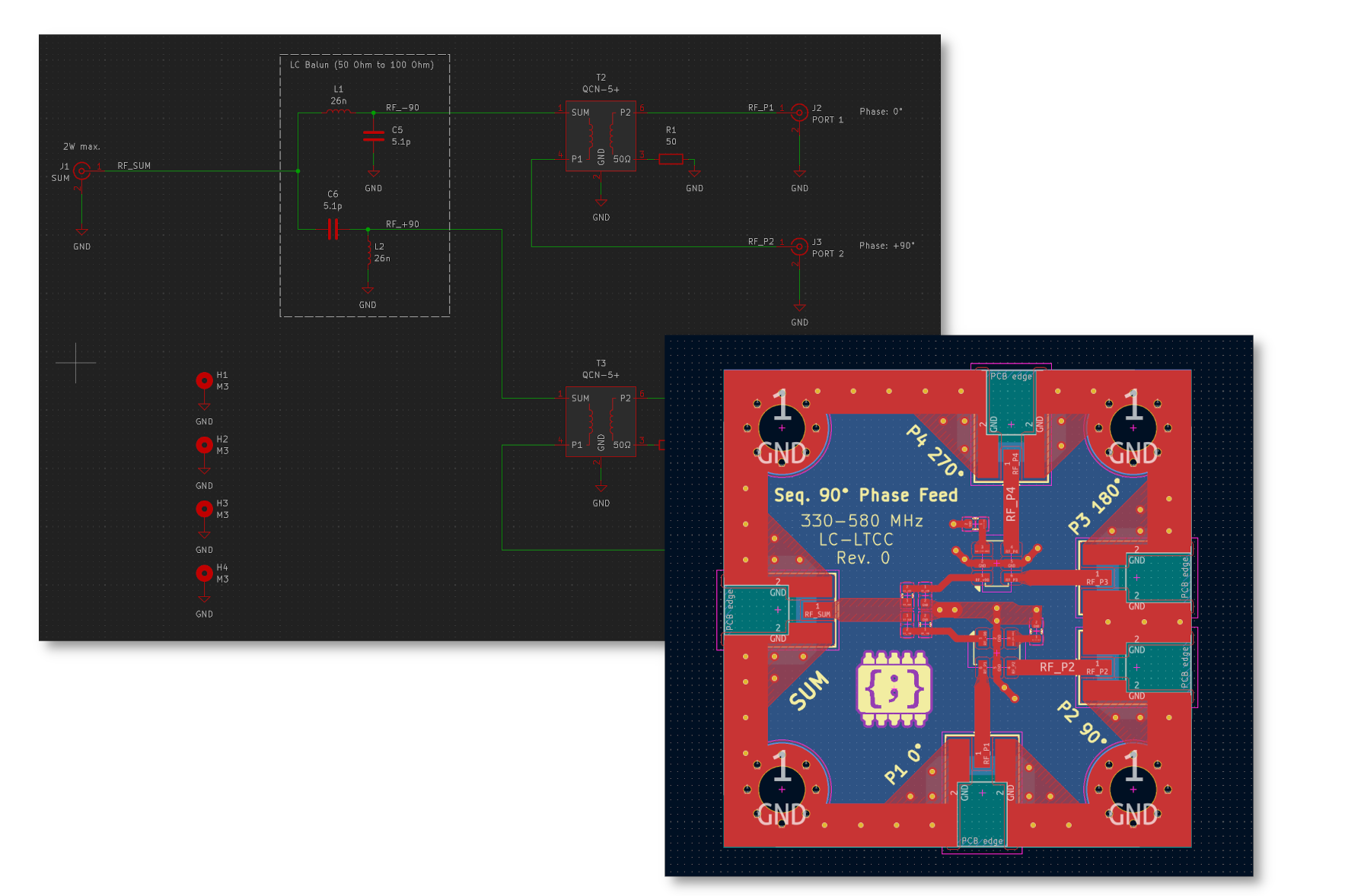 Figure 7: Schematic and PCB in KiCad 10.
The selected passives are automotive 0402 ceramic-core RF inductors (Murata LQW15AN) and NP0/C0G dielectric capacitors (Murata GCM1555), selected for their RF performance and thermal stability. MMCX connectors are used because of their size and mechanical stability.
The PCB was manufactured by JLCPCB with the following stackup: 0.8 mm thickness, 2 layers (35 µm) with ENIG plating, FR4 substrate. The PCBs used for the measurements were hand-soldered.
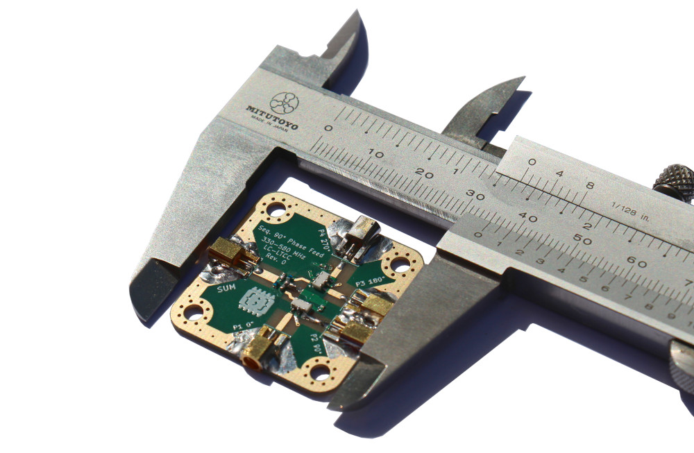 Figure 8: Close-up of the assembled PCB rev. 0.
Note: on the rev. 0 of the PCB, the QCN-5+ footprints are mirrored. They need to be assembled upside-down.
Measurements
Hardware testing was performed using an RF Vector Network Analyzer (LiteVNA-64, SOLT calibrated). The measurements included:
- Relative phase between all output pairs
- Output amplitude balance
- Power loss (above −6 dB)
All unused port were 50 Ω-terminated during each measurement. The isolation between the output ports was not measured.
The plot below shows the insertion loss and phase of each output port. Ideally, at the center frequency of the carrier, the S21 magnitude should be −6 dB (perfect quarter-power split) and the phases should be exactly 90° apart (perfect quadrature).
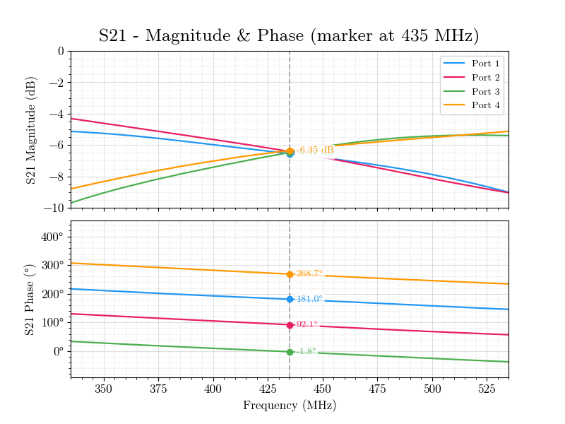 Figure 9: Plot of the S21 magnitude and phase, 335 MHz to 535 MHz.
The measured results are consistent with simulation predictions, with minor deviations attributed to PCB tolerances, connector transitions, and cable repeatability.
Conclusion
A compact sequential phase feed network was successfully implemented using commercially available hybrid couplers and LC passives. The measured performance is consistent with simulation predictions and meets the phase and amplitude balance requirements for a functional circularly polarized link.
Links
- Github repository: https://github.com/CGrassin/uhf_quadrature_feed_network
Auteur : Charles Grassin
What is on your mind?
Sorry, comments are temporarily disabled.
No comment yet!