Presentation
Lidars (LIgh Detection And Ranging) measure distances by illuminating the target with laser light and measuring the reflection with a sensor. When combined with a mechanical way to aim the beam, they can output 2D or 3D point clouds.
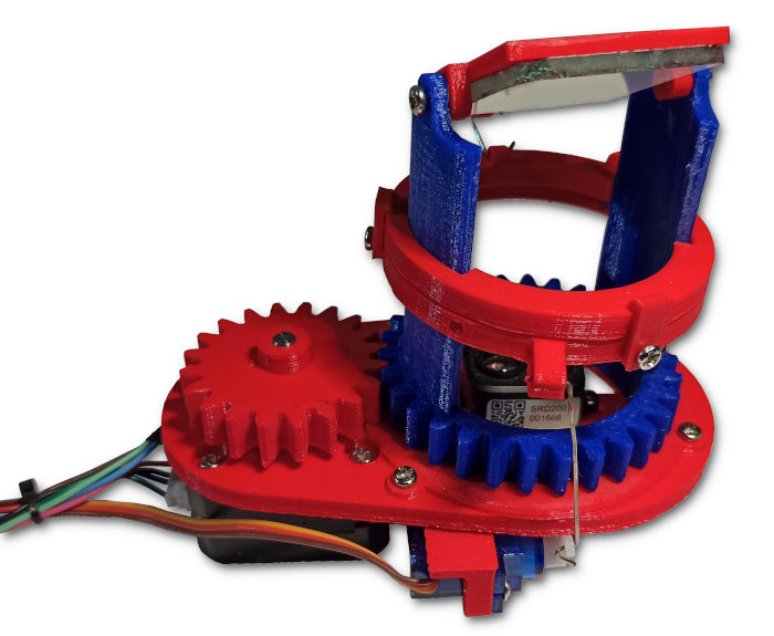 My open-source 3D lidar sensor.
This data is very useful for robotics or autonomous vehicles for instance, when trying to navigate in a complex environment. It is often combined with camera feeds and other sensors, to compensate for the limitations of each technology.
3D lidars are often expensive and not easily available to hobbyists. Hence, I designed and built a 3D-printable, open-source Lidar to experiment with this technology.
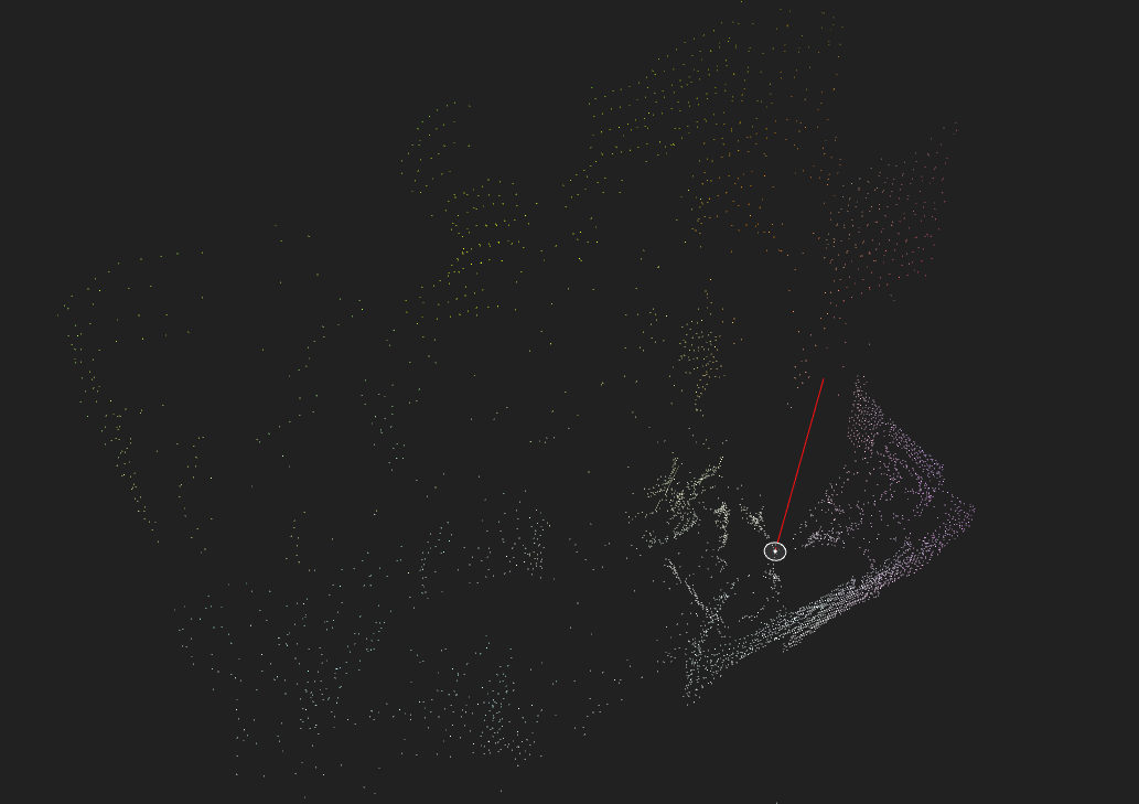 A typical Lidar image, taken with the unit built for this project.
In a previous project, I made a basic 3D Lidar scanner by moving a Lidar Lite sensor with a DIY pan/tilt mount. This iteration improves on this idea with a better mechanical design to achieve much faster scanning rate and higher resolution.
This article describes the design, construction and usage of this sensor. This project's sources and files are released on GitHub.
Video
This video shows the project:
Design
This section describes the design and construction of this sensor: mechanical, electronics, firmware and code.
The device's specifications are:
| Specification | Value |
|---|---|
| Resolution | ρ = 1cm, θ = 0.15°, φ = 0.3° |
| Max. range | 12 m (8 m for TF-Luna) |
| Power supplies | 12 V @ 1 A and 5 V @ 200 mA |
| Data rate | 100 Hz |
| Data interface | Serial over USB @ 115200 baud |
| Rotational speed | Max. 150 RPM, recommended 60 RPM. |
| Physical dimensions | 85 × 115 × 125mm, 250 g (ignoring electronics) |
| BOM cost | ~$40 |
Mechanical
The core idea with this design is that there is no moving electronic part. To achieve this, a mirror reflects the laser beam to and from the Lidar unit. To implement this concept, the delicate part is that there has to be 2 completely independent axes: yaw and pitch/tilt.
I modeled it with SolidWorks:
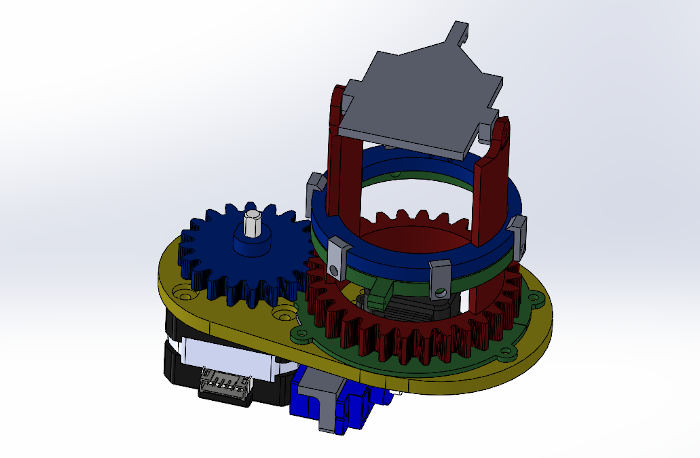 3D model in SolidWorks
In order to get independent control of both axes of motion, my design uses an assembly that works in a similar fashion to helicopters' swashplates: the motion is transferred from the stationary servo-motors to the rotating mirror through an intermediary sliding interface.
The yaw motor is a NEMA 17HS4023 "pancake" stepper motor. The tilt actuators are a pair of cheap 9 g servos.
All the parts where 3D-printed on my Anet A8 with 0.2 mm layer height, in PLA. Support material should only be activated for the rotor. Light sanding may be needed on some parts to get a perfect fit.
To reduce the amount of friction, I put a drop of medium viscosity silicone oil on the base-rotor interface.
Additional hardware is required:
- 40×40 mm piece of mirror,
- 15 M3×6 mm screws,
- Paper clips for the linkages (bending patterns are in the projects files),
- 2 M2.5 screws.
This video shows how the mechanical system moves:
Electronics
The electronics are based on a STM32 board commonly referred to as "blue pill". This 32-bit chip is much faster than the Arduino (72 MHz vs 16 MHz clock) and has several hardware serial ports, which is mandatory for this project.
This is the complete circuit diagram:
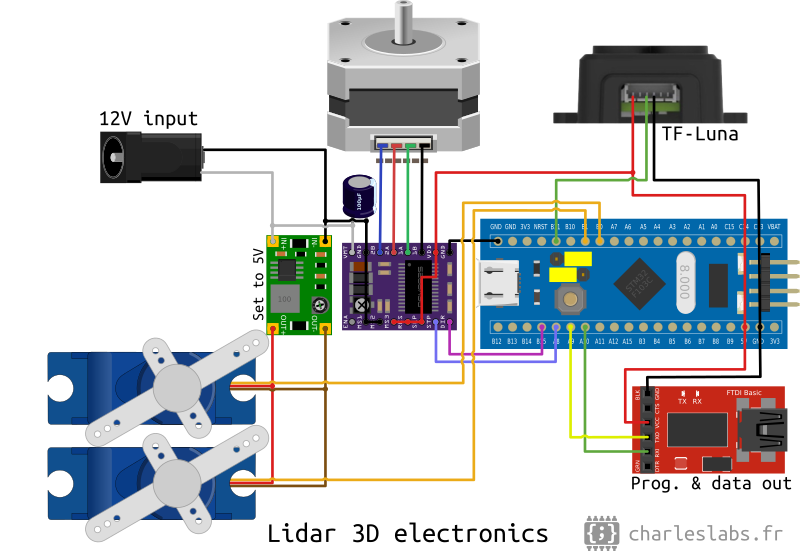
I used a TF-Luna Lidar, but it should be fully interchangeable with the more common TF-mini. This sensor uses ToF (time of flight) with laser bursts in order to measure the range with a resolution of 1 cm for less than $20. The beam width is about 2.3°.
The stepper motor driver is a DRV8825 module. The maximum phase current must be adjusted with the potentiometer to achieve reliable movement without motor heating.
To supply 12 V, I used an old laptop charger. A "mini 360" DC-DC buck converter module is used to power the servo-motors from the 12 V rail.
I built this circuit on a breadboard.
Note: The STM32 could probably replaced with an Arduino Mega. However, my code is currently incompatible with this board (pin assignments are different).
Firmware (MCU code)
The micro-controller's firmware does 3 things: drive the motors, convert the measurements to Cartesian coordinates and send them to the computer through a serial link.
Because of the Lidar's geometry, there are some transformations to figure out the direction of the lidar beam. For the yaw axis (θ), it is trivial:
![$\Theta \text{ [rad]} = \frac{\text{Steps in current turn}}{\text{Steps per turn}} \times 2 \pi$](/projects/20201024_Lidar_3D_v2/theta_equation.png)
For the tilt axis (φ), the math is a bit trickier. First, the servo motors pushes a linkage that lifts the carriage on the rotor, that changes the pitch angle of the mirror through another linkage. This equation is an approximation of this relation:
![$\alpha_{mirror} \text{ [deg]} = \frac{\text{Servo arm length}}{\text{Mirror axis length}} \times \alpha_{servo} + \text{Init. angle} \approx -0.3 \times \alpha_{servo} + 71$](/projects/20201024_Lidar_3D_v2/alpha_mirror_equation.png)
Then, from the angle of the mirror, we can compute the angle of the laser beam relative to the horizontal:
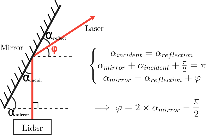
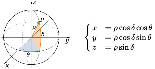
Finally, using the spherical to Cartesian coordinates system conversion formulae, it outputs the position of the point on the serial port:
Interestingly, the TF sensors also output the strength of the measurements, from 0 to 65535. This information is added to the Lidar's serial output, and may be use as a confidence value, for instance.
Hence, this is typical output into the serial terminal (x, y, z and signal strength separated by tabulations):
44    24    8    8347
37    27    8    6910
31    29    7    7839
...
To program the micro-controller, I use the Arduino IDE with stm32duino, using a serial to USB converter, as shown in the diagram. Note that the jumpers must be in the configuration BOOT0=0 and BOOT1=1 for programming (see on the electronics diagram).
Software (3D Lidar viewer)
Finally, to acquire and display the Lidar data, I created a visualization software using Processing. It is a very convenient open-source Java framework made for 2D or 3D graphical user interfaces and renders.
LidarViewer reads the serial port to get the data; displays it as a 3D point cloud we can zoom, pan, rotate and move; and saves it to a file so we can use it later on (in Meshlab for instance).
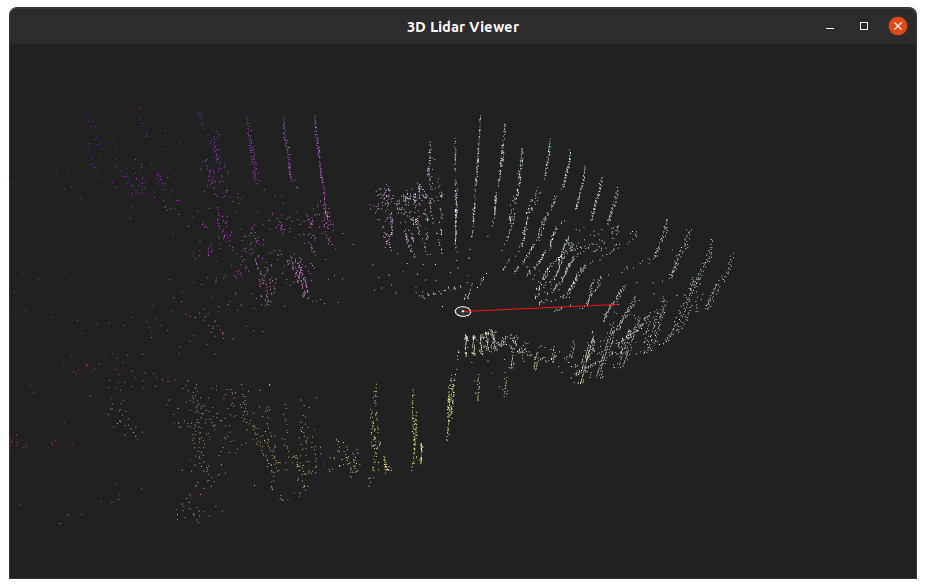 The interface of the 3D Lidar viewer software during a scan.
The key bindings are: arrow keys or mouse to move the camera, [S] to save the data (opens a file selection window) and [X] to clear the points.
The clip hereunder shows how the scanning looks in action.
Conclusion
This new iteration of my Lidar experiments improves a lot on my previous attempt by virtue of the better mechanical construction.
Advantages
The biggest advantage with this design is the versatility, thanks to its construction. Because we have full control over the yaw and tilt axes, we can tailor the scanning method to our needs, in software. For instance, we can perform very high resolution, slow scans, if the scanning rate is not a concern. On the contrary, we can achieve very fast speeds (up to 300 RPM) with a coarse resolution, and fill the point cloud by staggering the measurements. We could even do active tracking or any other way of using both axes of motion.
It is also quite inexpensive, easy to replicate as a result of using 3D-printing and common parts and very capable.
Limitations
The main limitation is the mechanical tolerances that are required for the 3D-printing process. This introduces some slop in the measurement, and makes a lot of noise at high speeds. This could of course be improved by machining it in metal for instance, but it defeats the purpose of this project.
There is another drawback in the Lidar's current geometry: the tilt axis' aperture is limited to about 45°: about 20° from the horizon in both directions. This could probably be optimized, but it cannot reach 180°. However, for use in robotics for instance, it is the zone of interest anyways. Hence, this is only a limitation if the lidar is intended to do full scans of room, for instance.
Links and sources
Author: Charles Grassin
What is on your mind?
Sorry, comments are temporarily disabled.
#1 NotARussianSpy
on October 27 2020, 16:10
#2 HappyThanksgiving
on November 26 2020, 11:03
#3 CountZ
on December 30 2020, 13:51
#4 Author Charles
on December 31 2020, 11:51
#5 CountZ
on December 31 2020, 12:32
#6 OliveaCaen
on February 5 2021, 18:36
#7 ikhwan
on June 22 2021, 11:26