Preliminary research
The human hand has a very delicate and complex structure. It is made up of a total of 27 individual bones connected by joints and ligaments, and operated by muscles situated in the hand and wrist. This allows us to perform a wide variety of movements.
In addition to this innumerable patterns of action, the hand also gives feedback to the brain through sensory nerve pathways. These feelings (pressure, vibration, touch, temperature and pain) are indispensable to interact with our environment and keep us safe.
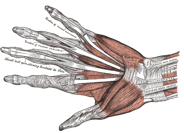 The muscles of the left hand from "Anatomy of the Human Body" by Henry Gray (1918)
To replace it, the commonly available prosthetic hands used to offer limited functionality: only opening/closing all fingers at once with mechanical control. About 10 years ago, more advanced fully robotic prosthetic hands were brought to the market. They offer more features, such as individual control of the fingers using myoelectric sensors, feedback, etc. However, those benefits come with a very high cost (often upwards of $ 50,000). This greatly limits the access to this technology.
More recently, thank to the democratization of 3D-printers, there have been several open-source/open-hardware projects to develop limb prosthesis: the Open Hand Project, OPENBIONICS, etc. This community brings great benefits for those in need of prosthetic limbs as they create affordable and functional systems. Additionally, it also generates new ideas that will undoubtedly improve the commercial models.
As a preliminary study, an interesting piece of information to consider is the additional features desired for future models from current users of prosthetic hands:
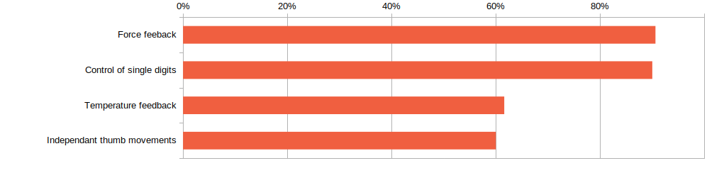 Survey data from "Results of an Internet survey of myoelectric prosthetic hand users", by Prosthetics and Orthotics International [1]
A prosthetic hand project is a must-do for any mechatronics enthusiast: it involves some complex mechanical design in CAD, electronics and some programming. Furthermore, any new idea could provide benefits to those in need for these systems. This article describes my own open-hardware hand project.
Mechanical designmagnetorquers
A degree of freedom (DOF) is a unique way in which a feature can move. A single joint can have 6 DOFs (3 translation and 3 rotation movements). The human hand is considered to have 27 DOFs in total: 16 in the fingers, 5 in the thumb and 6 in the wrist. With the currently available technology, we are not able to match this with sufficient force, fluidity and precision. The objective of my mechanical design is to reach a good compromise using widely available parts, in order to maximize the actual usability while minimizing complexity.
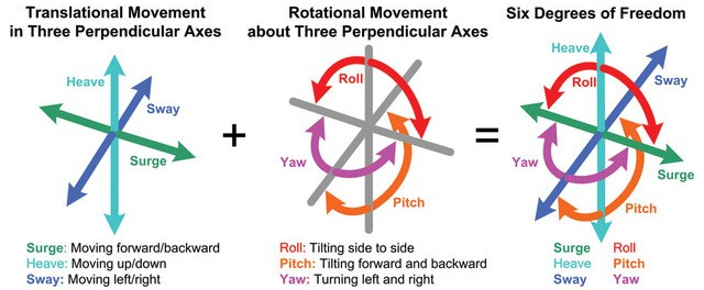 Six degrees of freedom, picture by Honeywell
The mechanical design is the hardest part of this whole project due to the huge complexity of the human hand. The starting point is the choice for the joint actuation method. There are 2 main ways commercial prosthesis achieve this:
- "Hard" joints: the joints are coupled to the actuators using gears or solid linkages.
- Compliant joints: the joints are coupled to the actuators using strings, like the tendons the human hand uses. The main advantage of this method is that the fingers can better conform to the shape of the objects which result in better gripping force, but reduced accuracy.
I chose compliant joints. For simplicity, I only implemented force in the closure of fingers. They are sprung back to the open position with small medical rubber bands.
I designed the hand with an iterative process starting with the finger and going backwards to the wrist. The 3D-printing technology make this quick prototyping very easy to achieve, with better end-result. This a render of my CAD model in SolidWorks:
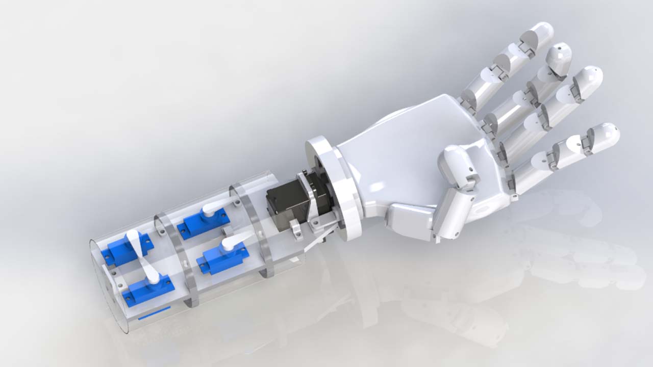 SolidWorks render of the 3D model
The actuators (servo motors) are situated in the wrist and the force is transferred to the tip of the fingers through the palm and fingers using artificial tendons. The tendons are 0.5mm nylon fishing wire, offering a tensile strength of more than 40kg. A larger, more capable, servo motor can rotate the hand 180 degrees.
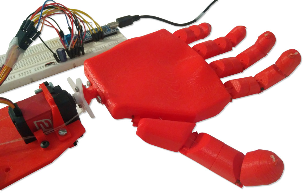
This is my 3D-printed prototype (printed on the Anet A8 and Skeleton 3D):
The servomotor actuating the tendons are standard SG90. Considering their advertised 1.2kg/cm torque (0.12N.m), they deliver an ideal holding force of 600g (5.9N) per finger.

In the same form-factor, better servos are available. For instance, the MG90 metal geared servos would theoretically give each finger nearly twice the force (1.1kg) instead! Of course, the actual force would be lower than this due to the non-ideal transfer.
Material-wise, the hand is 3D printed in PLA. PLA is a versatile bio-plastic which is both easy to print and offer a good strength. However, it is quite brittle and has a very low softening point (about 50°C). For a future version, PETG plastic would be a better suited material: more durable, more impact resistant and better thermal characteristics. There are less common 3D printable materials and processes that could be even better for this application: carbon fiber reinforced nylon for instance.
Electronics
Feedback sensors
In my prosthesis, I decided to implement two kinds of feedback that are naturally present in the human hand: force/pressure and temperature.
Temperature feedback
Regarding temperature, I included a standard 10k thermistor in one of the fingers. It has an operating range of about -90°C to 130°C. It is a NTC (Negative Temperature Coefficient) meaning that it acts as a variable resistor. From the resistance, we can compute the temperature. To display the information, I chose to simply use a RGB LED.
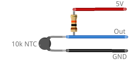 Circuit diagram for the thermistor
Pressure/force feedback
To give a primitive sense of touch, I initially planned to put a force sensitive resistor (FSR) at the tip of the finger. They are little disks that, similarly to thermisors, act as variable resistor, depending on the force applied on them. However, this would have added a lot of internal wiring and generally make the hand more complex.
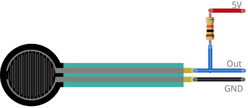 Circuit diagram for the FSR (not used in my design)
Instead, my alternative is to sense the current that the servo motors use. Because the mean current is directly proportional to the force they apply, this also gives a force feedback to the controller without adding significant complexity to the hand.
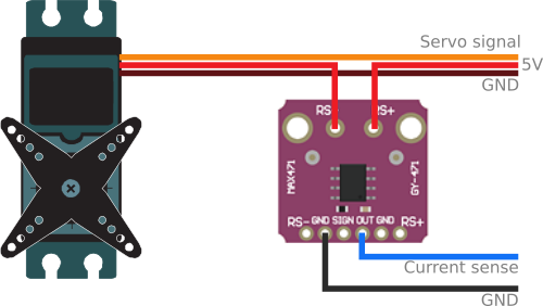 Circuit diagram for the MAX471 current sensing module
The only difficulty here is that most servo control boards use pulse width modulation (PWM) to drive their motor. The duty cycle determines how much force the motor applies. To show this waveform, this is an oscilloscope measurement of the ouput of the MAX471 when a large torque is applied on the servo:
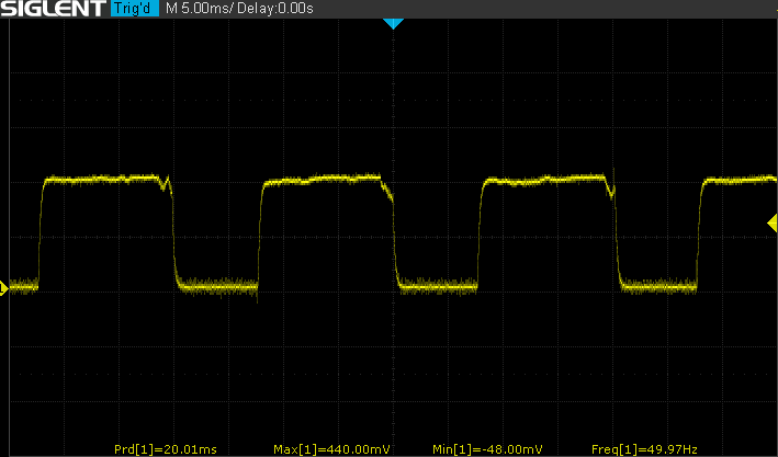 Current waveform of a MG90S servo, measured with a MAX471 (1 mV corresponds to 1 mA)
The value we actually need to determine is the arithmetic mean of this waveform. To do this, we need to sample N points over a period (or an integer number of periods), and use this formula:

This easy to implement in Arduino C++ code:
unsigned long measureMeanCurrent(int pin, unsigned int period /*in µs*/){
    unsigned long startTime = micros(), sum = 0;
    unsigned int n = 0;
    while(micros() - startTime < period) {
        n++;
        sum += analogRead(pin);
    }
    return sum / n;
}
Note: for SG90 or MG90 servos, period equals 20000 µs but if integration time is no concern, multiplying this value by a integer (2 or 3 typically) effectively filters the result.
With adequate filtering and calibration, this gives very reliable data. For instance, this graph shows the output value of this function when varying amount of force is applied to the servo arm:
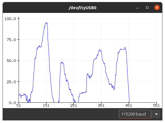 Force feedback measurements viewed in the Arduino serial plotter
We can use the same circuit and code simultaneously for multiple fingers.
This force feedback adds a way for the micro-controller to self-adjust to the load. This allows the hand to perfectly grip the object without requiring the wearer's active attention. For instance, when trying to grip light and fragile item (eg. an egg), the prosthesis could use its force feedback to determine the optimal gripping force, and maintain it. Similarly, when holding a solid object, the hand can self adjust using the feedback to provide a perfect grip, optimizing its power usage and durability.
Control with OpenEMG
Electromyography (EMG) is an electrodiagnostic medicine technique for evaluating and recording the electrical activity produced by skeletal muscles. OpenEMG is a project I started to make an open-hardware, easy to make, EMG module to capture muscle information from Arduino or any other micro-controller.
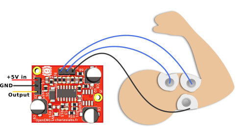 The OpenEMG electromyography sensor
In fact, this project is the very reason I originally designed OpenEMG. Click here to read the full article with the schematics, code example, PCB files, etc.
This graph shows the analog output value of OpenEMG for a series of muscle contractions (the biceps in this case):
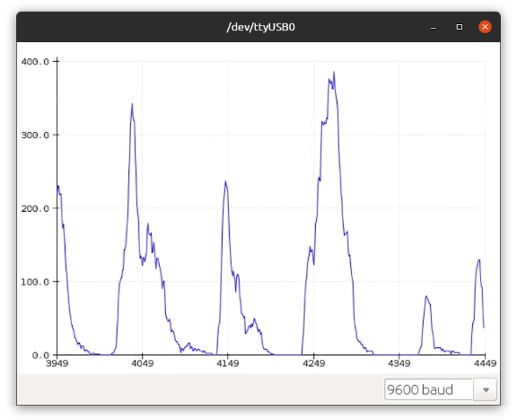 Biceps activity measurements with OpenEMG, viewed in the Arduino serial plotter
A minimum of six EMG sensors would be required to get full control of the hand. However, using even more sensors could make the control feel more natural.
Microcontroller and software
For the control system of the hand, I used an Arduino Nano board with a ATmega328P 8-bit micro-controller. A closed loop control loop is required to read the input (EMG sensors and force-feedback) and generate an adequate output (movement of the fingers with the servos).
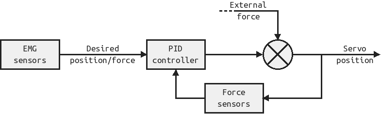
The control algorithm is a simple proportional–integral–derivative (PID) controller with a strong proportional term. It is easy to implement in C++ code and, with careful tuning, it gives stable and fast output.
In the case of more EMG sensors, the movement of a single finger will depend on several values (because the readings wouldn't likely be independent). I think that this problem is a great candidate for machine learning: based on a lot of EMG data and the corresponding movement that the user expect, a model could be computed. This could decrease the amount of physiotherapy and make the experience more natural by adapting it to the user instead of the opposite.
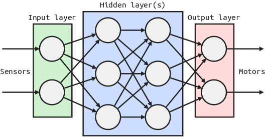 An artificial neural network model for hand control
Power Management
To get the best possible energy density, the obvious choice is to use Lipo batteries. They also have the advantage of being able to handle large current bursts. The largest capacity that I had that could fit in the wrist section are 2000mAh 2S. This gives about 14.5 Wh of available energy.
A power grip requires about 1.2W per finger.
Result
This video shows the hand in action, performing basic movements:
The build cost of this design is about $30.
There is a lot I would like to explore in the future, based on this prototype. For instance, adding a proximity/video sensor to improve the prosthesis' independence, requiring less focus from the user for basic tasks (grabbing, opening a door, etc.). Some more DOFs are required, especially in the thumb, to be able to perform a wider range of actions.
Download
Click here to download the archive with all the 3D files (in STL, SolidWorks and STEP formats):
Notice: the content of this archive is provided "as-is", under the terms of the CC0 1.0 Universal (CC0 1.0) Public Domain Dedication license.
Bibliography
- Craig L. Taylor, Ph.D. and Robert J. Schwarz, M.D (1955). The Anatomy and Mechanics of the Human Hand. link to website
- Pylatiuk, C., Schulz, S., & Döderlein, L. (2007). Results of an Internet survey of myoelectric prosthetic hand users. Prosthetics and orthotics international, 31(4), 362-370. https://doi.org/10.1080/03093640601061265
- Mahdi Elsayed Hussein (October 2014). 3D Printed Myoelectric Prosthetic Arm.
- Reinis Geizans (May 2018). Developing 3D Printed Prosthetic Hand Model Controlled by EMG Signal from Forearm.
Author: Charles Grassin
What is on your mind?
Sorry, comments are temporarily disabled.
#1 Sebastian
on March 25 2021, 12:34
#2 Sebastian
on March 25 2021, 12:35
#3 Author Charles
on March 27 2021, 17:21
#4 Arnab
on August 5 2023, 13:11
#5 ag
on May 26 2025, 1:32