3D Lidar Scanner

Electronics - 28-10-2017

Update (17/10/2020): I made a new Lidar sensor. It has a lot of improvements compared to this one: link to the article.

Presentation

In order to perform an accurate 3D scan of a room/environment, I created this lidar (LIght Detection And Ranging) turret as a 3-day project. Based on the Garmin™ LIDAR-Lite v3, it scans its surroundings using an infrared laser beam and rotating it using small servomotors. This video shows the completed apparatus:


The scan time mainly depends of the step size we chose. It ranges from less that a minute to about 30 minutes (full resolution, more that 32,000 data points). The accuracy of the measurements is about 1 cm, up to 40 meters in range.

The acquisition and visualization software I created for this project can extract the point cloud for further use (3D Printing, CAD software, etc.).

Hardware

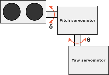
Hardware-wise, the scanner is rather basic: two 9g micro servomotors control the roll and pitch rotational axes. The brackets that hold them together are 3D printed.

Servomotors construction

Download the 3D files (SolidWorks & STL)

Concerning the electronics, I used:

  • Arduino Nano: the controller for the turret. It drives the servomotors and control the lidar while doing a small amount of computation to output the point cloud.
  • LIDAR-Lite v3: a compact, high-performance optical distance measurement sensor.
  • 9g SG90 Servomotors: actuators to rotate the lidar. Although these weak motors are a major bottleneck to the system, I used them simply because I already had them. Some more powerful and less "wobbly" servos would definitely enhance the quality and speed of the capture.
  • 650uF capacitor: this large electrolytic capacitor prevents the micro-controller from rebooting during the current spikes that both the lidar and the motors create.

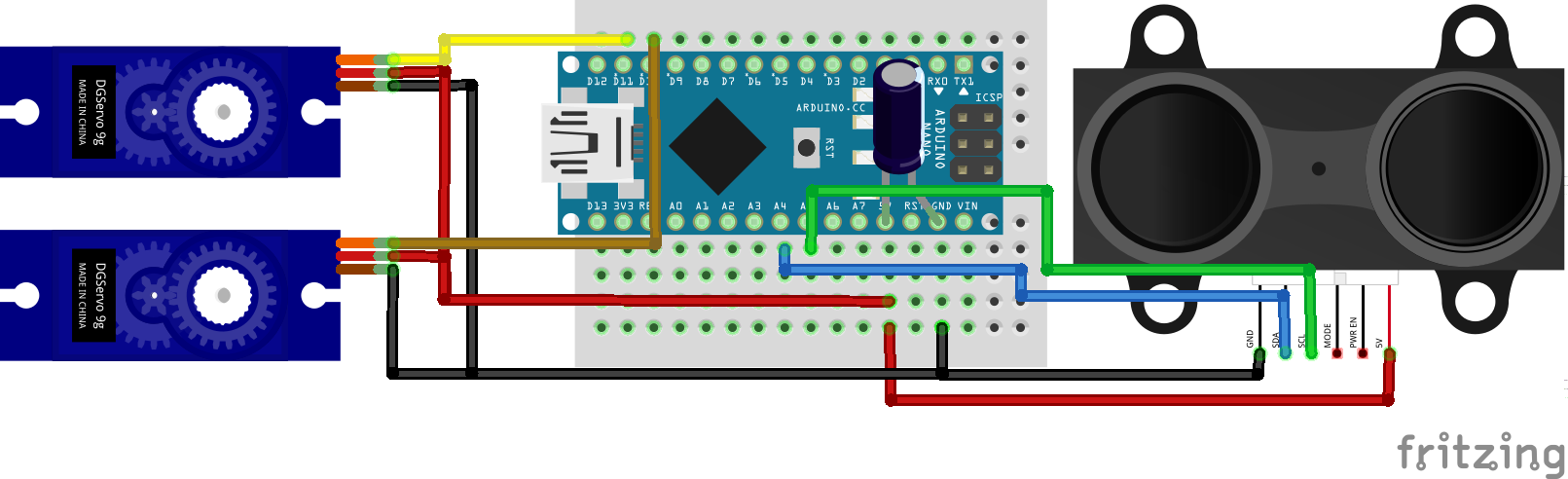
This is the wiring diagram for the my lidar turret:

Wiring diagram of the Lidar

Software

The software that operates this project is divided into two distinct bits of code: the micro-controller side and the data acquisition/visualization software. It is of course fully open-source, and you can download the complete source for both parts by clicking on this button:

Download the source

Arduino code

Thank to the Servo.h and LIDARLite.h Arduino libraries, the code to control these elements is made much easier. The basic work-flow of the code is the following:

Init. lidar, servos and serial;
for YawAngle = 0 to 180:
  for PitchAngle = 0 to 180:
    Compute_coordinates();
    Send_value();

The micro-controller only knows the angles of the servos and the distance to the obstacle. A small amount of computation is required to convert the yaw angle, pitch angle and range information into much more usable X, Y and Z coordinates.

Spherical coordinates conversion formulas

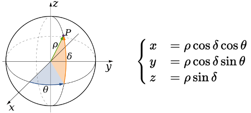
Using these spherical to Cartesian coordinates system conversion formulas, it outputs the position of the point on the serial port.

Data acquisition and visualization software

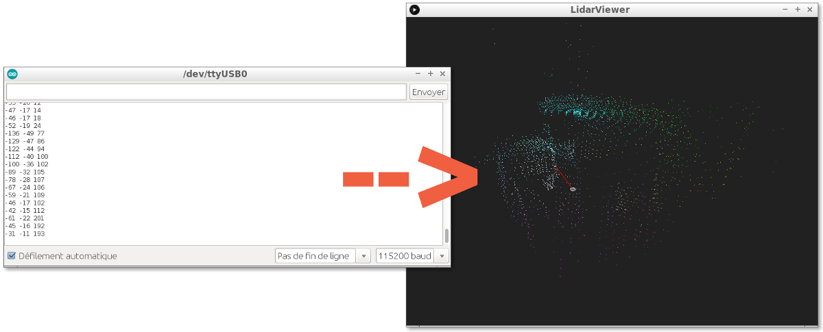
In order to collect, display and use the turret, I created a software using Processing. It is a very convenient open-source Java framework made for graphic related work. LidarViewer reads the serial port to get the data; displays it as a 3D point cloud we can zoom, pan, rotate and move; and saves it to a file so we can use it later on (in Meshlab for instance).

LidarViewer software

Author:


What is on your mind?

  • #1 SHAHID

    How to save a file that can be open in Meshlab or CAD

    on November 21 2018, 1:37

  • #2 Author Charles

    My LIDARviewer Processing sketch is a basic 3D viewer I created for this application and does not include a lot of features. You can save the point cloud by pressing the S key, so you can import it into Meshlab. However, you can't open an existing point cloud in it. However, this would be a pretty easy to add feature. I recommand not to take this code as-is and to have a look at the Java. There is probably a lot of room for improvement!
    Good luck!

    on November 22 2018, 7:23

  • #3 Hardrone

    Hello,
    1) I am facing "'import' does not name a type"error in .pde file (Under LidarViewer.pde)
    2) I am getting "Datestamp >> >> nack" message for each detection, instead of the distance measured in Serial Monitor (Under LidarTurret.ino)
    3) How to get the output in terms of point cloud out the distance measured? I mean, what you have shown is, you are getting a continuous point cloud generation with respect to the distance measured.

    on February 6 2019, 11:18

  • #4 Janu

    Hey how did you view the data points in processing? we have to use same code used in Arduino for processing as well?

    on February 8 2019, 5:32

  • #5 Jaime Candelaria

    Amazinig project Charles
    I am currently working with the same lidar but with a raspberry pi and 2 servo motors in order to have the pitch and yaw angles. I keep noticing that, when scanning, the sensor reads distances that do not make any sense (like 10,000cm when scanning a small room or box). Were you faced with this problem? How did you over came it?
    Thanks a lot!

    on February 18 2019, 20:44

  • #6 Author Charles

    @Janu: the visualization software is the "LidarViewer.pde" sketch, while the Arduino code is the "LidarTurret.ino" sketch.

    on February 19 2019, 21:40

  • #7 Author Charles

    @Jaime Candelaria: Thank you! No I did not encountered this problem... Does it always do it, or is it some intermittent error? Have you put the capacitor on the power lines of the lidar? I draws a large current on its measurements, and may have an erratic behaviour if this is not dealt with. What I would do is try my sketch if you have an Arduino laying around. It is a much simpler system than the Raspberry Pi, and could help you rule out an electrical issue.

    on February 19 2019, 21:46

  • #8 janu

    Hi. the file is not getting saved for me. I pressed S key and I searched processing install directory. I couldn't find my file. All other keys are working for example x key for erasing and other movement keys except s key. where exactly the file will be saved.

    on March 5 2019, 6:47

  • #9 Author Charles

    Hi janu! For some reason, Processing may be trying to save the file somewhere else. A quick workaround is to replace the path in the "void saveToFile()" method by hard-coding the fileName variable with a path of your choice (for instance, String fileName = "C:/file.xyz"; on Windows or String fileName = "/home/<your user name>/file.xyz"; on Linux). If you are on Linux, you need write permission on the folder.

    on March 5 2019, 10:53

  • #10 Paul

    hi Charles first of all thank you for your work, 2nd I wonder if I use different servo motors would this change the results ??

    on March 15 2019, 0:01

  • #11 Author Charles

    Hi Paul! The SG90 servo I used are the cheapest servo motor you can buy. They are actually pretty bad because their control loop tend to oscillate and not be very stable. Additionnally, they have plastic (nylon) gears. Hence, different servos would probably be better. Of course, the mount must be adapted.

    on March 20 2019, 8:04

  • #12 Alexander

    Hi Charles, how would I change it to only include a one dimensional movement, for example only PITCH and no YAW

    on March 27 2019, 20:57

  • #13 Alexander

    Hi Charles, sorry I forgot to mention that thank you for this! Also might I ask what you mean by the mechanical wobble?

    on March 27 2019, 20:58

  • #14 Alexander

    Also might I ask my friend what the s[15] means?

    on March 27 2019, 22:49

  • #15 Olga3

    Hello Charles, Thanks for this project. But I was wondering why the final result is like two scans inside each other? The ceiling is like two and not one and I notice in your screenshot it is the same. How we can overcome this problem? Thanks in advance for the help.

    on June 17 2019, 23:46

  • #16 olga

    Hello Charles, Thanks for this project. But I was wondering why the final result is like two scans inside each other? The ceiling is like two and not one and I notice in your screenshot it is the same. How we can overcome this problem? Thanks in advance for the help.

    on June 17 2019, 23:48

  • #17 Dario

    Hello, I based my project in this schema but I changed the Pan and Tilt kit so for that reason the servo motors changed the coordinate system, I could resolve this problem just switching cos and sin parameters but the final result also change because its symetric (like a mirror) its easy to fix just calculate the symetric function and thats it. I would like to say thank you for sharing this project it was really helpful for me , but if somebody will change something should be very carefull because it could make a lot of difference.

    on July 29 2019, 13:18

  • #18 Author Charles

    Thank you Dario, glad you were able to make it work! Yes, trigonometry can be tricky...

    on July 30 2019, 7:25

  • #19 pablo

    hello, I wanna use it for 3d mapping with a phantom4 drone, it is possible I hope you can help

    on December 26 2019, 4:55

  • #20 Rob

    Hello,
    Nice code. I was wondering if you could help me with using this same code to identify what an object or shape could be. Say a cylinder, box, etc...

    on April 18 2020, 3:17

  • #21 Richard

    Hi Charles, great project and thanks for sharing, I've looked around at some of your other projects and they look great too. I was just wondering about the lidar readings do these have to be calibrated (offset) given the axis of motion you are turning through? I couldn't see anything in the code. I assume the measurement is from the lens face.

    on May 28 2020, 16:11

  • #22 Author Charles

    Hi Richard! You are indeed correct: my Lidar is off-center, and we would need to account for this to get more accurate. We can actually see the deformation from this effect in my video. It is not very noticeable at long range (meters away), but at less than a meter, straight objects get curved. Fixing this is a pretty simple math transformation (trigonometry). This was a quick project, and the precision did not matter too much!

    on May 28 2020, 16:49

  • #23 Richard

    Hi Charles, yes I figured you had no need as you had accomplished what you set out to do and as you say a simple transformation will adjust this... I look forward to seeing more of you work!

    on May 28 2020, 17:36

  • #24 Richard

    Hi Charles, yes I figured you had no need as you had accomplished what you set out to do and as you say a simple transformation will adjust this... I look forward to seeing more of you work!

    on May 28 2020, 17:37

  • #25 Jacob

    Hi Charles
    Im new to this, but when I try to compile the LidarViewer code for the Lidar all I get are numerous errors. Is this becuase the code is old, since I had to change the extension from .pde to .ino?
    Many Thanks
    Jacob

    on August 4 2020, 15:36

  • #26 Author Charles

    Hi Jacob,
    LidarViewer is a processing sketch. It must be launched using the processing software.
    The Arduino code is LidarTurret.ino

    on August 7 2020, 8:52

  • #27 Jacob

    Dear Charles
    Thank you for your response, does the LidarTurrent code collect the data and the Lidarviewer code process it?
    Also is it possible to swap the servo motors for stepper motors?
    Many Thanks
    Jacob.

    on August 25 2020, 10:06

  • #28 Author Charles

    Hi Jacob,
    You are right, LidarTurrent collects the data and converts it to cartesian coordinates while LidarViewer simply displays the result as a point cloud.
    Of course, you could use stepper motors. The only "issue" is that the hadware will probably become a bit more complex. Also, you have to make sure to avoid doing too many revolution so the cables do not get tangled!

    on August 26 2020, 7:33

  • #29 Jimmy

    Hi Charles.
    Thank you for posting this, your work has been incredibly helpful.
    I do have one question though, in Lidarviewer how do you save the processing output of the point cloud?
    Thank for in advance for taking your time to read these questions and quires.
    Kind Regards,
    Jimmy.

    on August 31 2020, 7:20

  • #30 Jimmy

    Dear Charles,
    Another question I have is, do I run the Lidar turrent Arduino sketch first and then the processing sketch?
    Kind Regards
    Jimmy.

    on August 31 2020, 7:25

  • #31 Author Charles

    Hi Jimmy,
    In LidarViewer, you can save the point cloud by pressing the "s" key. This creates a ".xyz" file. See questions above for this file's location.
    The Arduino sketch runs continuously and scans the room while sending the coordinates to USB with a Serial port. You could just capture this data with the Arduino Serial Monitor. LidarViewer is a Processing sketch that read the Serial Port and does a nice real-time 3D display of the Lidar scan. It doesn't do anything too fancy! Hence, when running it the Arduino should be connected to the PC.

    on September 1 2020, 23:20

  • #32 Jimmy

    Dear Charles,
    Thank you for your response. I am a bit confused with changing the file path in the processing sketch.
    I am unsure how you implement the change as I have tried this: saveToFile("C:\Users\Jimmy\Documents\Processing"); and it wont work, and I have tried the same but without quotation. How would implement the file path change.
    Also for the Lidar viewer to work, do you have to run the lidar turret sketch first and wait for it to finish the loop, then unplug it, then run the Processing sketch. Im unsure and am having issues with the processing sketch saying the Com port is busy.
    Thank you very much for your time and help.
    Much appreciated,
    Jimmy.

    on September 2 2020, 13:27

  • #33 Casey

    Hey Charles!
    So we are trying to run a similar project, but have the LiDAR scan an object for a 3D point cloud map. You're project is a great reference! But whenever we try running the file in processing, all that happens is a Blank Screen comes up in the Lidar Viewer window. Even if we unplug the Ardiuno it doesnt even show "Not connected" like its suppose to. Anyway we could get in contact with you to pick your brain? It'd be a great help in our Senior Design Project.

    on March 15 2021, 20:58

  Back to projects

Related articles