Reaction wheels principles and usages
In the past, I made a system to experiment with a satellite attitude control mechanism for CubeSats: magnetic torquers (also known as magnetorquers). These use an existing magnetic field, such as the Geomagnetic (Earth's) field, to apply torque on the spacecraft and achieve stability. I made Helmholtz coils to simulate the changing electromagnetic environment: see article here.
In this project, I want to explore another way for spacecrafts to get active attitude stability and control: reaction wheels.
 During Servicing Mission 3B in March 2002, astronauts Michael Massimino (left) and James Newman (right) replaced one of Hubble’s four Reaction Wheel Assemblies, which help turn the spacecraft. Credits: NASA
The physics backing reaction wheels is very simple. It is based on the conservation of angular momentum. An electric motor is attached to a flywheel which, when its rotation speed is changed, causes the spacecraft to begin to counter-rotate proportionately, following this equation:


ω is the angular speed. The I factor is the moment of inertia, which describes the opposition that the body exhibits to having its speed of rotation about an axis altered by the application of a torque (turning force). It's mathematical expression is:

For instance, for a solid cylinder of radius R about its central diameter with constant, this expression becomes:

For more complicated geometries (such as a spacecraft), it can be computed using CAD models.
Spacecraft use this effect by storing a large amount of angular momentum in at least 3 flywheels (for 3 axes control), and change their own angular speed and attitude by slowing/accelerating the flywheels.
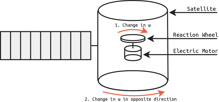 Diagram of a satellite with reaction wheels.
This provides a high pointing accuracy which is required, for instance, to capture the breathtaking observations of the Hubble Space Telescope.
My model
To experiment with reaction wheel control, I made a one-axis model of a satellite capable of active detumbling and attitude control. I made sure that it is easy to reproduce by only using off-the-shelf parts and 3D-printing.
Mechanical build
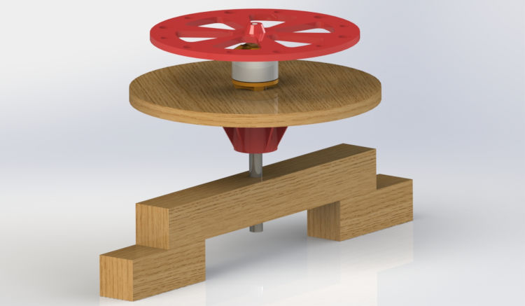
I designed my model in SolidWorks to be 3D-printed. This is a render of the CAD:
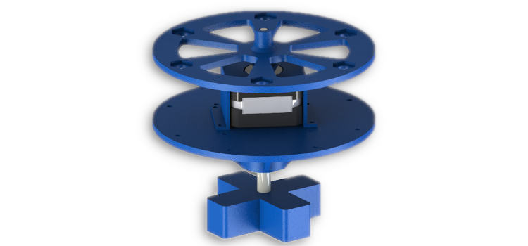 3D render of the model in SolidWorks.
The central element to this design is the motor. After having mixed results with a BLDC (see below), I chose to use a NEMA 17 stepper motor (same type as those used in 3D-printers). It is quite heavy (about 150 g) but has a high torque and sufficient max rotation speed.
To get the free-spinning ability that the satellite would have in micro-gravity, it is attached to a vertical axis with 608ZZ ball bearings. The motor is coaxial, turning the flywheel.
There are 4 parts to 3D-print: base, satellite disk, motor holder and flywheel. I 3D-printed mine on an Anet-A8 with IceFilament PLA, at 0.2 mm layer height. The only part requiring support is the motor holder.
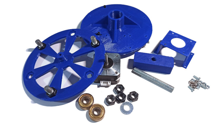 3D-printed parts and hardware for the model.
Additional hardware is required to build it:
- 8 M3×6 mm screws,
- Some M8 nut and bolts,
- A 65 mm piece of M8 threaded rod,
- 2×608 bearings (skateboard bearing),
- Zip ties to secure the wiring.
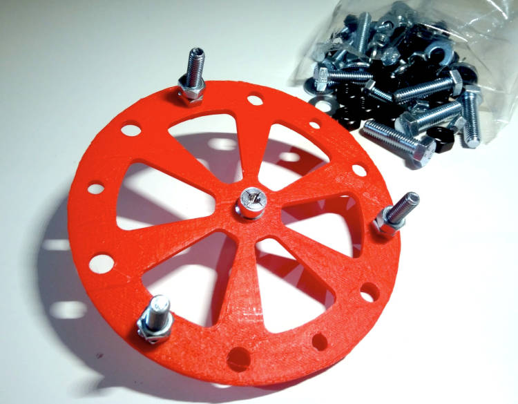
The main design consideration for the design of the flywheel is that the motor has a maximum angular speed and torque. When we reach the max speed, we lose the ability to compensate for additional motion in this direction. This state is called saturation, and to avoid it, satellites often thrusters to create an opposite angular speed, so that the motor can speed up or slow down to an adequate regime (desaturation). Another way of reducing the occurrence of saturation is to make the moment of inertia of the flywheel (I factor) as big as we can. However, because the motor has a limited torque, there is a balance to be found. Hence, to keep a lot of flexibility during the test phase, I 3D-printed a light wheel with 8mm holes:
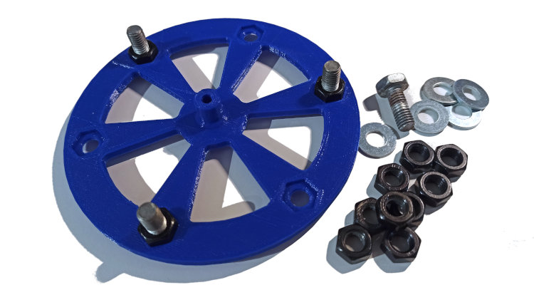 The flywheel with some M8 hardware to adjust its moment of inertia.
By placing M8 screws, nuts and washers around the flywheel, we can fine-tune its moment of inertia. For instance, with 3 M8×20 mm screws (10 g each) and 3 M8 nuts (5 g each), my flywheel as a moment of inertia of about:

The "satellite" disk itself is 80 g plus the motor:

This means that the moment of inertia ratio is about 0.7. Hence, to stabilize the satellite from 1 RPM to 0 RPM, the flywheel must change its own angular speed by 1.5 RPM in the opposite direction through the help of the motor.
This is the fully assembled model:
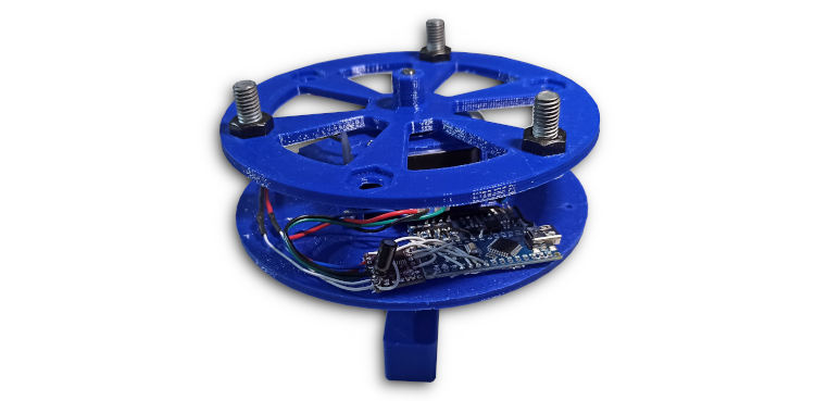 Fully assembled reaction wheel model.
Electronics
The electronics in this model have several tasks:
- Measure the current angular speed : the MPU6050 gyroscope/accelerometer MEMS chip,
- Drive the stepper motor: a DRV8825 module,
- Run the control algorithms: the ATmega328 microcontroller, on an Arduino Nano board.
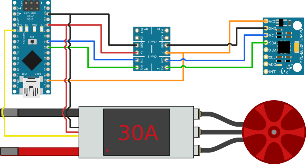
This is the complete electronics wiring diagram:
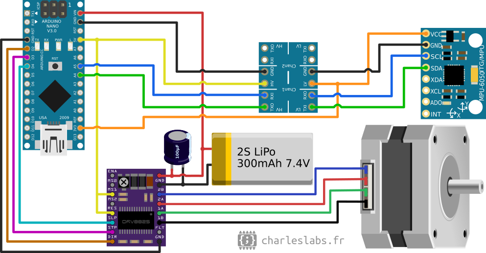 The electronics circuit diagram.
It gets powered with a 2S LiPo battery: a "Fullymax 601742" with a capacity of 300mAh/2.22Wh in my case, intended for quad-copter drones. A 3S would improve the torque of the stepper, but they are not common in a small form factor.
Because the MPU6050 is 3.3V logic and this Arduino is 5V, I had to use a MOSFET-based bi-directional level converter board.
The DRV8825 has a potentiometer that sets the current limit to drive the stepper motor. This needs to be set first to get reliable movement without skipped steps or motor heating. I set mine to 750 mV, which corresponds to 1.5 A.
I soldered everything directly on the disk with minimal length of wire:
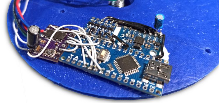 Electronic circuitry soldered on the disk.
Microstepping is set by the M0, M1 and M2 pins of the DRV8825. I got best result with a 1/4 microstepping (set with M1=5V). The maximum torque and speed depend on this value.
Control algorithms
The Arduino (C++) code needs to control the rotational speed of the satellite (for stabilization/detumbling), and also have precise control on the attitude of the device.
Speed control (de-tumbling)
The MPU6050 outputs the yaw rotation speed. We need to drive the stepper motor accordingly.
This is a typical closed-loop system: the stepper motor affects the rotation speed of the model (forward path), which is measured by the gyroscope (feedback path). It is well described by a mathematical/engineering field known as control theory.
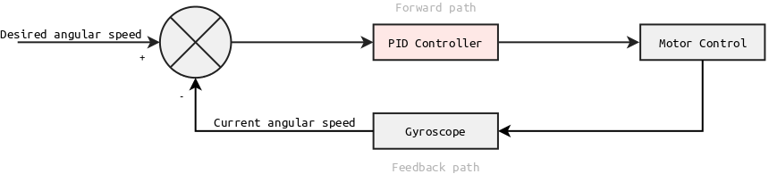 A block diagram of the rotation speed feedback loop.
We need to determine a transfer function for the controller that allow us to achieve stability, taking into account the physical parameters of our model. The simplest and most commonplace algorithm is the PID (proportional–integral–derivative) controller.
In my case, I used a PD controller (PID with a zero I coefficient). It is called every time a gyroscope measurement is requested (every 10 ms) and its output is always added to the current motor speed.
The coefficients need to be set appropriately. I tuned it empirically, following those steps:
- Increase the P-term with coarse steps until it starts oscillating and back up,
- Increase the D-term with coarse steps to improve stability (reduce oscillations/overshoot),
- Fine tune both P and D terms to improve the system's response.
I implemented a rolling average filter on the speed readings to dampen the effect of vibrations on the output of the gyroscope.
Note: changing the moment of inertia of the flywheel (i.e. adding or removing M8 hardware) should not require re-tuning the algorithm. Indeed, multiplying the PID coefficients by the ratio of change in the moment of inertia should be sufficient. Of course, this is only true if there are no other parasitic effect (such as skipped stepper steps for instance).
Attitude control
Then, once the system is stable, we may want to ask the MCU to reach a precise angle. We could write a completely separate controller with the attitude as input, but this is quite inefficient as we would have two different controllers to tune based on the same physical parameters.
A better solution is to use the previous controller to handle the angular speed, and always determine a setpoint that reduces the positional error. We still need another controller to determine this ideal speed at any given time, but it is mostly independent from the physical parameters. Hence, it is easy to tune.
This is the block diagram for the complete controller logic:
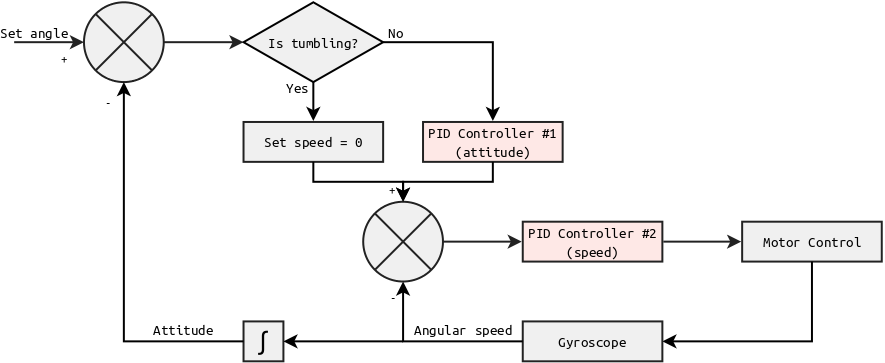 Block diagram of the full controller logic.
Therefore:
- The PID controller #1 takes an angle as input and outputs a speed target to reach this attitude optimally,
- The PID controller #2 takes a speed as input and outputs a speed command for the motor control logic.
To determine whether the system is tumbling or not, my code uses a very simple 2-states finite state machine (FSM). The criteria for the transitions is the current angular speed, with some hysteresis.
 Finite state machine diagram for the tumbling logic.
Implementation
The full C++ code for this controller is available in the GitHub repository.
It uses a straightforward implementation of a PID controller, and a custom "hacked" version of the AccelStepper Arduino library to allow speed control instead of position control as intended in this library.
Demo
This clip shows how the different parts of this model move in relation to each other (when the battery is disconnected).
Video clip demonstrating the free movement of the model.
Detumbling/Stabilization
This next clip shows the speed stabilization/detumbling. The microcontroller is held in reset while some clockwise momentum is added to the disk. After about 1 second (boot up time), the controller starts and gets the rotation speed to 0 RPM as fast as possible.
Video clip demonstrating the detumbling capability.
We see that to counteract this clockwise motion, the motor sped up the disk in the clockwise direction (creating counterclockwise acceleration). Once the speed reaches 0, the motor has to keep that speed.
Attitude control
Next, to show the attitude control, the MCU is asked to turn exactly 180° every 2.5 s:
Video clip demonstrating the attitude control. There is some overshoot in the controller.
An important fact to note here is that the disk does not gain extra speed in the process. Hence, in the absence of parasitic effects (drag), these kinds of maneuvers do not contribute to the wheel's saturation.
Of course, as long as it does not reach saturation, the system is also able to compensate for external forces and maintain a set attitude:
Video clip demonstrating the reaction to external forces applied on the model.
Every time the disk is pushed in a direction, the wheel has to speed up in the same direction in order to cancel the rotation.
Saturation
Finally, this clip shows the saturation state:
Video clip demonstrating the saturation state of the model.
The wheel is already at its maximum speed when additional movement in the same direction is added. Because it can go any faster, the disk is stuck into a tumbling state. There is nothing the controller can do to solve this situation.
A real satellite would use a secondary attitude control system (generally, thrusters) to desaturate the wheel by adding rotation speed in the same direction as the wheel. Thrusters require fuel: it is often a limitation for the duration of missions.
Conclusion
This model shows really well the effect of reaction wheels. It is quite easy and inexpensive to build. Various parameters can be adjusted to evaluate their effect on this system's response: the PID controller gains, the moment of inertia of the flywheel, the phase current of the stepper, the gyroscope signal processing (Kalman filtering, ...), etc.
As shown in tests, it is fully able to stabilize and control its attitude.
In the future, I also want to experiment with more aerospace attitude control systems with:
- A model rocket with a gimbaled thruster. I already started experimenting with this through a physics engine simulator, see article here...
- A model rocket with several cold gas thrusters actuators powered by compressed air.
Links
- GitHub repository containing the code and CAD: https://github.com/CGrassin/reaction_wheel
Previous Version of the Project
This section describe the previous version of this project. It is kept for reference only, the new version described above is much better (more stable, less saturation problems).
To experiment with reaction wheel control, I made a one-axis model of a "satellite" capable of active detumbling and attitude control.
Physical build
The body of the satellite is depicted by a wooden disk. To get the free-spinning ability that the satellite would have in micro-gravity, it is attached to a vertical axis with 608ZZ ball bearings. The motor is coaxial, turning the flywheel.
 Render of the 3D model from SolidWorks.
The main design consideration for the design of the flywheel is that the motor has a minimum and a maximum angular speed. When we reach one of these extremes, we lose the ability to compensate for additional motion in this direction. This state is called saturation, and to avoid it, satellites often thrusters to create an opposite angular speed, so that the motor can speed up or slow down to an adequate regime (desaturation). Another way of reducing the occurrence of saturation is to make the moment of inertia of the flywheel (I factor) as big as we can. However, because the motor has a limited torque/max. load, there is a balance to be found. Hence, to keep a lot of flexibility during the test phase, I 3D-printed a light wheel with 6 and 8 mm holes:
By placing M6 or M8 screws, nuts and washers around the flywheel, we can fine-tune its moment of inertia. For instance, with 3 M6×35 mm screws and 6 M6 nuts, my flywheel as a moment of inertia of about:

The "satellite" disk itself is 180 g:

This means that he moment of inertia factor is about 0.4, hence, to detumble the satellite from 1 RPM to 0 RPM, the flywheel must change its own angular speed by 2.5 RPM in the opposite direction through the help of the motor.
Electronics
To make the model work, we need:
- Some way to measure angular speed and position: the MPU6050 gyroscope/accelerometer MEMS chip,
- Some way to actuate the flywheel: a 920kv A2212 brushless DC motor, controlled by a 30A RC aircraft electronic speed controller (ESC),
- A controller: the ATmega328 microcontroller, on an Arduino Nano board.
The full wiring diagram is:
The Arduino is powered by the 5V BEC (battery eliminator circuit) included on the ESC. Additionally, because the MPU6050 is 3.3V logic, I had to use a MOSFET-based bi-directional level converter board.
I soldered everything directly on the disk with minimal length of wire.
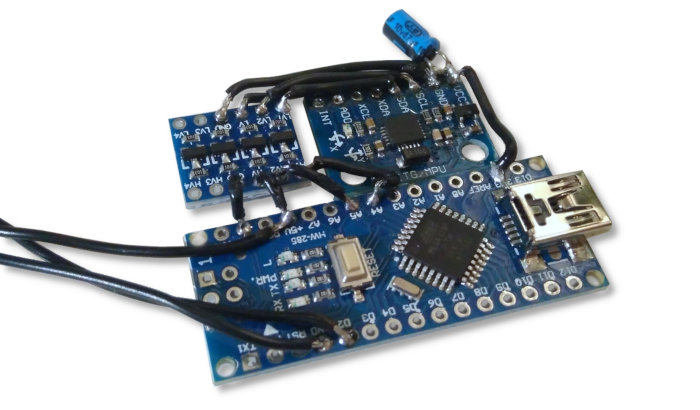
The electrolytic decoupling capacitor smooths the 3.3V supply of the MPU6050.
Code
This contraption is a fairly basic one-axis closed loop system: the speed/position of the disk is read by the gyro, and controlled by the rotation rate of the flywheel. I chose to use a simple PID (proportional–integral–derivative) controller as a control algorithm.
The tricky part is that the ESC I used can quickly accelerate the flywheel, but has no active braking. This means that the systems reacts very differently depending on the direction of the error it tries to compensate. The workaround I implemented is to use two PIDs: one for positive error and one for negative error. This is known as an asymmetric PID controller.
This block diagram represents my control loop:
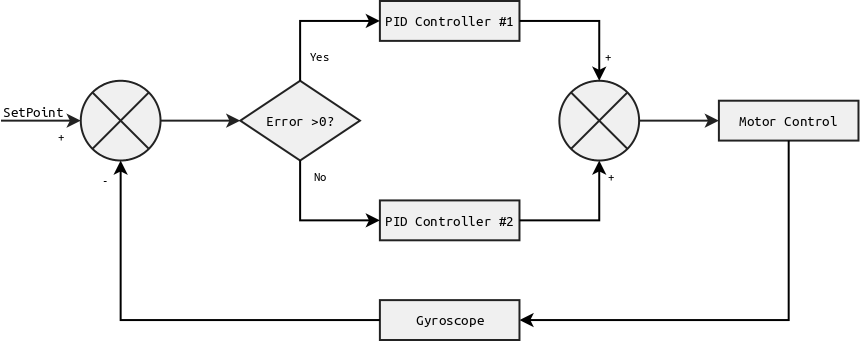
The PID controllers where tuned empirically. Their gain are somewhat interdependent, which makes the tuning process less obvious and prone to oscillations. A better solution would be to use a purpose-designed controller, especially as the physical parameters and relation are known and repeatable.
This is implemented in Arduino (C++) code.
Tests
This video shows how the different parts of this model move in relation to each other (no power is applied).
Detumbling and Stabilization
The controller's default behavior is to keep the satellite's angular position around 0° (the angle is was powered at).
It mostly manages to keep stability around its set point. There is however some drift in the gyro measurements which result in drift on the set point over the course of tens of seconds.
Control
In the next video clip, instead of receiving a simple "stability around 0°" order the controller is instructed to:
- When the red LED on the Arduino is lit, the target angle is 45° to the left (clockwise),
- When the green LED on the Arduino is lit, the target angle is 0°.
The order changes every 2 seconds.
The clockwise "bouncy" behavior is the result of a too high derivative (D) coefficient of the PID controller, which was required to get good angular stability. This issue does not arise in the counter-clockwise direction (the direction of the flywheel).
Author: Charles Grassin
What is on your mind?
Sorry, comments are temporarily disabled.
#1 Sanasar
on July 11 2020, 9:39
#2 John
on March 8 2021, 10:23
#3 Author Charles
on March 8 2021, 21:25
#4 Stan
on February 1 2022, 17:58
#5 Lauren
on August 1 2022, 16:57
#6 Vivek
on January 20 2024, 12:41
#7 Dayan
on February 11 2024, 11:28
#8 VIGNESH
on March 12 2024, 21:25
#9 Deep
on July 3 2024, 7:58