Update (05/07/2020): added tests with JLCPCB manufactured filters
What is a hairpin filter?
Electronic filters are circuits which remove unwanted frequency components from the signal to enhance the signal-to-noise ratio. They are notably useful in the radio UHF range, to remove undesired transmissions and therefore improve the receiver's relative sensitivity.
An SDR (software design radio) such as the RTL-SDR with good filtering and an adequate antenna (and possibly external amplification), can pick up very low amplitude signals such as satellite transmissions.
Filters are usually made of discrete components (capacitors, inductors, etc.) in certain arrangements to form low-pass, high-pass, band-pass or band-cut. As frequency grows, this becomes increasingly unreliable. Microstrip filters are a higher-frequency alternative that uses the physical shapes and positions of transmission lines to affect their attenuation on specific frequency ranges.
There are several geometries used to construct distributed element filters, but all have the common property of causing a discontinuity on the transmission line. These discontinuities present a reactive impedance to a wavefront traveling down the line, and these reactances can be chosen by design to serve as approximations for lumped inductors, capacitors or resonators, as required by the filter.
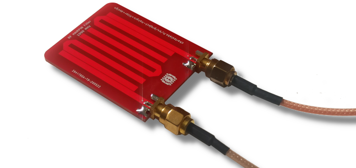 One of my 1090 MHz hairpin microstrip filters, made using this generator.
The hairpin topology uses parallel-coupled lines and behaves like a band-pass filter used to isolate the bandwidth's frequencies from parasitic signals. It takes up relatively low board space and it quite easy to build compared to other band-pass microstrip topologies such as the interdigital filter.
There are a lot of papers describing the mathematical models of microstrip filters. However, it is quite hard to extract a recipe and it will often result in poor performance. Hence, I created this Javascript tool to generate them using a sensible experimental model.
Update (26/05/2020): The generator can now directly generate a Kicad footprint (kicad_mod file).
The microstrip hairpin filter generator
Enter your desired elements length in the following form to generate an SVG or Kicad file. Use the form under to compute the element length for any given frequency.
Preview:
This hairpin must be printed on one side of a standard double sided 1.6 mm thick PCB. The back side must stay copper coated and be connect to the ground. Remove the solder mask on top of the filter.
On the SVG file, the horizontal line at the bottom of the page is 150 mm, to check scaling after printing/importing.
The generated topologies are designed to be used with standard female 50Ω SMA board-edge connectors. Solder the connector center signal pins to the hairpin feeder tracks and the ground pins to the bottom side.
This tool is under MIT license.
Technical details
Video
This video shows the project:
Simulation/Model
I made an openEMS model of my hairpin filter. Thank to finite difference time domain analysis (FDTD), this model can be used to determine the S-parameters S11/S22 (reflected power) and S21/S12 (transferred power) for different element's length. Note that the return loss and transmitted power in either direction should be identical because the construction is completely symmetrical.
This animation shows the wave propagation with a Gaussian excitation function, simulated with this model (viewed in Paraview):
Running this code with Octave/Matlab is a better way to design a hairpin filter than my calculator but it takes tens of minutes per simulation, depending on the frequency range, mesh size and of course computing resources.
Download the code on my GitHub repository: https://github.com/CGrassin/hairpin_filter
Geometry
The following figure shows the structure of the hairpin filter:
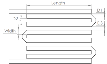
The dimensions I used are given is the following table.
| Dimension | 3 Hairpin |
|---|---|
| D1 | 0.25 mm (10 mil) |
| D2 | 2 mm (80 mil) |
| D3 | 2 mm (80 mil) |
| Width | 2.54 mm (100 mil) |
| Length | See formula below |
The length is computed on a formula I determined with experimental data using a quadratic regression curve fitting:
![\text{Length [mil]} = 4554 - 4.23 \times f_{center} + 1.17 \times 10^ {-3} \times f_{center} ^{2}](/projects/20181031_Hairpin_filter_design/eqn_len.png)
This gives good results up to about 1.5 GHz - more about this below.
Homemade PCB fabrication
To make my test hairpin filters, I used my quick prototyping method (click here to go to the article).
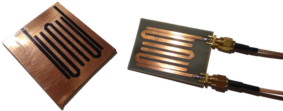 The masked copper board, ready for etching with ferric chloride, and the completed board with the SMA ports soldered
This method is not well suited to achieve the precision that is required for the UHF range. Better PCB quality will result in less losses, improved consistency and a sharper frequency response.
Professional PCB manufacturing
I also manufactured hairpins filters with the JLCPCB service. I fitted two different filters per board on the standard 10 cm×10 cm offer.
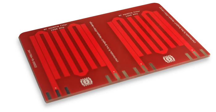
At the time of ordering, JLCPCB's material (FR-4 Standard Tg 130-140/ Tg 155) is specified with a diaelectric constant equal to 4.5. The solder mask's is 3.8.
To measure the transfer function of those filters, I use my DIY scalar network analyzer. I built it with an ADF4351 synthesizer, two RTL-SDR receivers and a VSWR bridge. It is controlled by a Python script. Link to the project: https://github.com/CGrassin/rf_network_analyzer
With this system, I can measure the magnitude of S21, the power transmission and S11, the reflected power.
This plot shows the measurements performed on 3 identical filters:
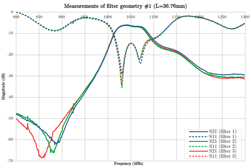
There are several interesting pieces of information to note here:
- The bandwidth is about 50 MHz,
- The lower cutoff is quite sharp, while the upper cutoff is quite a bit more round.
- The repeatability is very good, even with this non-RF controlled FR4 material.
It also shows that the bandwidth's attenuation is quite high (about -4/-5 dB). However, this is easily solved with a simple 10 dB LNA (low noise amplifier) added before or after the filter. Alternatively, the internal LNA in RTL-SDR's tuners should be able to deal with this, with a low NF (noise floor).
Four (or more) hairpins filters get a flatter bandwidth at the cost of more losses.
I also ran another set of measurement on the other, shorter geometry (higher frequency band, note the range of the x-axis):
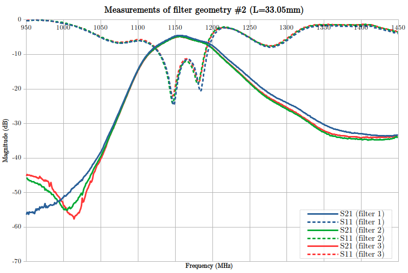
As expected, the center frequency is higher: about 1160 MHz vs 1050 MHz. The average loss in the bandwidth is about the same. However, it is less linear, which might be undesirable. The roll-off (in decibels per decade) is comparable to the first geometry.
Note: Solder mask should be removed on top of the filter. It may interact with the EM field. I forgot to do it in this case.
EMI mapping scan
I used my DIY EMI mapping method on one of my hairpin filters: see article here. This is the result, with an H-field loop probe:
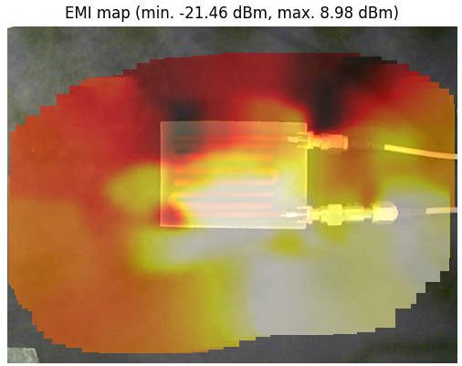 EMI near-field scan of Hairpin RF filter. A signal fully out of filter bandwidth is fed from the bottom SMA.
Fine tuning
The response of the filter depend of the diaelectric constant of the PCB material. To get a good estimation of your PCB's characteristic, the best way is to empirically determine your PCB coefficients by:
- Manufacturing a filter using my calculator at your desired center frequency -20% (length=l1) and measure its true center frequency (f1),
- Manufacturing a second filter at your desired center frequency +20% (length=l2) and measure its true center frequency (f2),
- Compute your PCB material characteristic with the simple linear regression formula:

You can then use this function to compute the length.
Because the relation between length and center frequency is nearly linear as long as the values are close, this gives very good results.
Using good quality PCB, my generator alone should get your center frequency within the bandwidth.
Limits
The lower frequency limit to hairpin filters is simply due to their physical size: below 900 MHz, it gets quite big and therefore expensive in terms of board space. Of course, with some tuning, it is possible to get much lower than this but discrete components may be a better choice.
The upper frequency limit is a bit more tricky: as frequency grows, the PCB material losses also grow. Above around 1.5 GHz, with conventional FR4, they usually get out of control. Additionally, the filter's cutoff shape gets gradually rounder and rounder. These two effects combined defeat the purpose of a filter.
However, distributed elements filters like the microstrip hairpin are commonly used in test equipment and satellite television reception for frequencies well above 5 GHz. This is made possible thank to well controlled PCB material, high quality manufacturing processes and a lot of engineering!
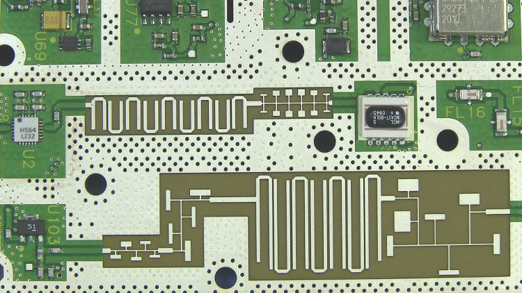 The PCB inside a 20 GHz Agilent N9344C spectrum analyzer, photo by Binarysequence on Wikipedia
Source code
The source-code for both the generator/calculator and the openEMS model is available on this GitHub repository: https://github.com/CGrassin/hairpin_filter
Sources
- Paul Wade (2011). Recipes for Printed Hairpin Filters, from http://www.w1ghz.org/filter/Recipes_for_Printed_Hairpin_Filters.pdf
Author: Charles Grassin
What is on your mind?
Sorry, comments are temporarily disabled.
#1 Duncan
on May 10 2019, 6:34
#2 Malik
on July 25 2020, 14:43
#3 Author Charles
on July 29 2020, 10:14
#4 Eugene Fischer
on November 17 2020, 5:13
#5 Author Charles
on November 17 2020, 7:48
#6 ukins
on April 1 2021, 7:18
#7 Jerry
on April 5 2021, 1:34
#8 Gerik
on May 4 2021, 15:28
#9 Eddie
on October 24 2022, 6:37
#10 Roshni
on July 23 2025, 7:47