Turbofan and EDFs
Most modern airliners use turbofan engines because of their high thrust and good fuel efficiency. The basic theory of operation of a turbofan is simple: a gas turbine generator (in the center) creates a lot of mechanical energy by burning fuel in a compressed air environment, in its combustion chamber. Most of this energy is used to drive a fan that pushes a large volume of air, creating a forward force.
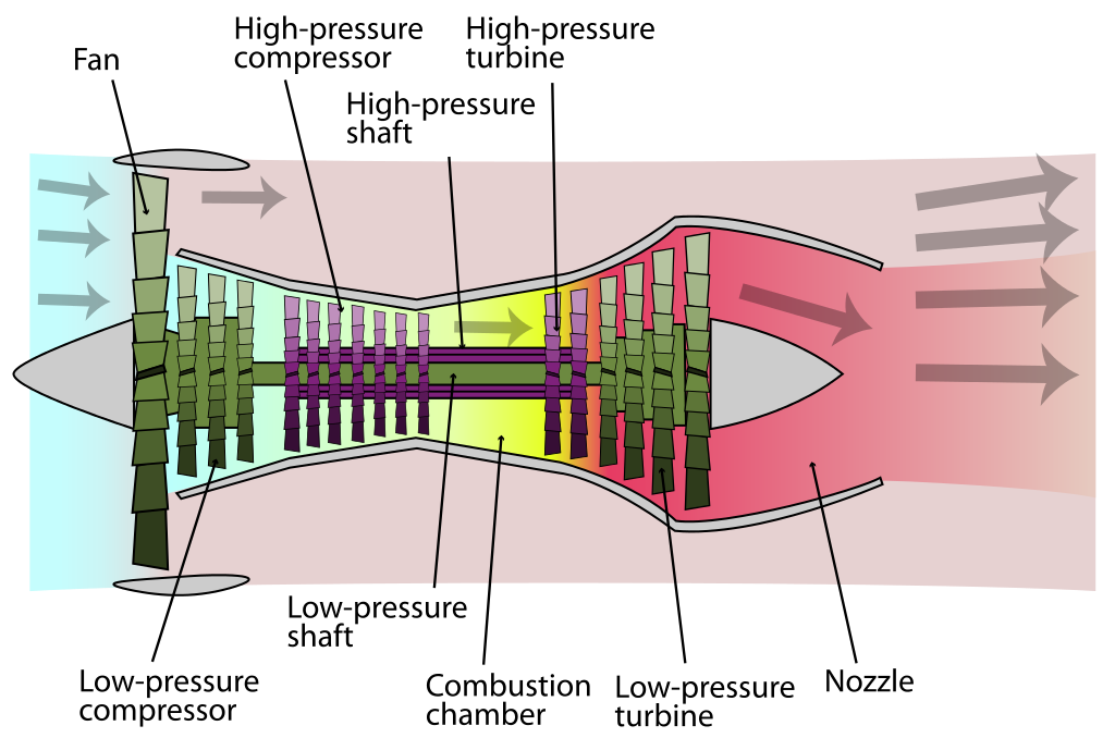 By K. Aainsqatsi - Own work, CC BY 2.5, https://commons.wikimedia.org/w/index.php?curid=4005530
In my case, I will be replacing the combustion chamber with a brushless DC motor (BLDC). Hence, my thruster is called an electric ducted fan (EDF for short). By reducing propeller blade tip losses, the ducted fan is more efficient in producing thrust than a conventional propeller of similar diameter, especially at low speed and high static thrust.
The point of this project is to explore the effects of some of the variables to design an efficient EDF motor by gathering some data with simulations and tests.
Design and Engineering
As a starting point and general guideline for the geometry, I referred to the paper "Hover and wind-tunnel testing of shrouded rotors for improved micro air vehicle design" by Jason L. Pereira (Doctor of Philosophy), 2008.
One on the feature I wanted to include in my EDF is reverse thrust capability. Thrust reversal is the temporary diversion of an aircraft engine's thrust providing deceleration. This capability does not make a lot of sense with an electric motor since we could simply reverse the rotation of the motor instead. However, I wanted to experiment with this. Additionally, most RC planes/drones ESCs happen to be irreversible.
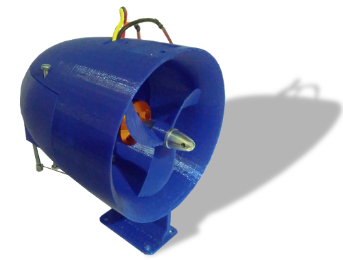
All of the parts that make up this engine are 3D-printed in PLA on my Anet A8 (including the fans, which are somewhat challenging to 3D-print with FDM technology).
CAD/simulation of the body
All dimensions depend on the radius of the fan blades. Generally speaking, the larger, the better, because they can spin slower for the same thrust output, resulting in less losses. I had to limit myself to 40mm for safety reasons, as the forces on the tips of the 3D-printed blades grow with their radius.
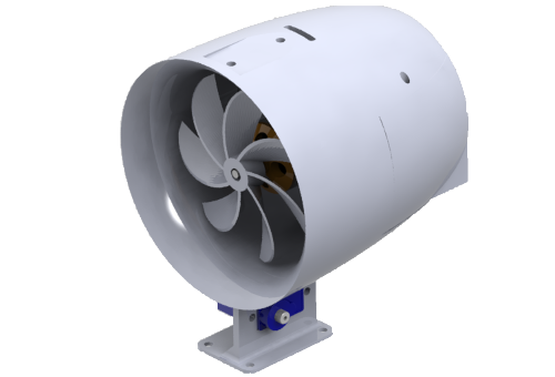
I used SolidWorks to model all of the body parts. This is a render of the assembly:
Computational fluid dynamics (CFD) is a branch of fluid mechanics that uses numerical analysis and data structures to analyze and solve problems that involve fluid flows. Solidworks has a module called SOLIDWORKS Flow Simulation that can simulate fluid flow, heat transfer and fluid forces on a 3D model. For the scope of this project, CFD is an essential tool to optimize the geometry of the engine's body for the intended operating conditions.
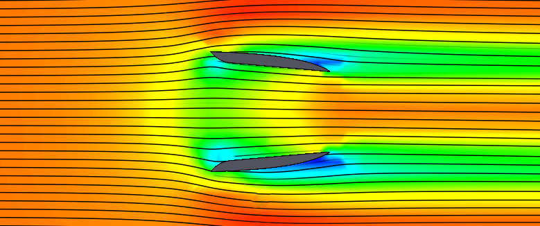
I ran several simulations and tweaked the curves to reduce drag. For instance, the following figure is a sectional view of the body in a constant laminar flow of air. The colors map the local pressure (red being high, blue for low). An area of low pressure behind a part "pulls" it backwards. Hence, the objective is to minimize theses zones.
I also ran dynamic simulations with a placeholder fan to view the vortices and the effects of the length of the duct on their occurrence.
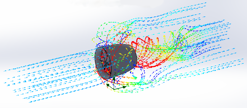
Thank to these CFD simulations, I was able to improve the shapes of some of the curves of the main body to limit the drag that would reduce the efficiency of this EDF in dynamic testing conditions.
Designing the fans
The fan that pushes the air was created using the "OpenSCAD Turbine Propeller Generator" by CorrugatorSupercilii on Thingiverse. OpenSCAD is open-source software that uses scripts to describe and render 3D models.
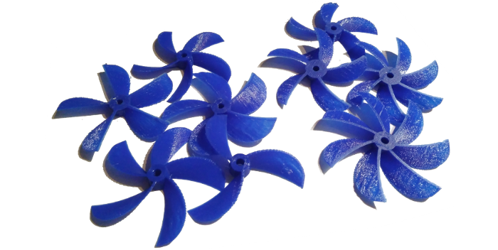
In a well-written SCAD script like this one, one can change some variables to affect the resulting 3D model. This gives great customizeability, as shown on the previous picture! This is fundamental for this project, as I want to tweak the characteristics to achieve the best possible efficiency. I eventually printed 6 fan configurations:
| # | Number of blades | Blade angle | Curved |
|---|---|---|---|
| 0 | 3* | 20° | Yes |
| 1 | 5* | 20° | Yes |
| 2 | 7* | 20° | Yes |
| 3 | 5 | 20° | No* |
| 4 | 5 | 25°* | Yes |
| 5 | 5 | 15°* | Yes |
The idea is to change the parameters one at a time to be able to compare their effect, and deduce the maximum efficiency. In the previous table, the asterisk symbol identifies the characteristic that is tested by the fan.
Although I could have also used CFD to optimize those parameter, I chose to actually measure their effect.
Electronics
The electronics of this project are basic RC components:
- A 920KV A2212 brushless motor,
- A generic 30A ESC (electronic speed controller),
- A SG90 servo motor,
- A Flysky FS-i6 RC remote+receiver to send the control signal to the ESC and servo motor.
The "KV" rating of the brushless motor indicates the rotation speed (in RPM) per input Volt. 920KV in very low for my EDF diameter. To achieve good thrust and efficiency, we would ideally need at least triple that. However, I chose this motor for safety reasons: my fan are 3D-printed and may shatter if they turn too fast. Hence, I will only be looking at relative comparisons between the fans, and not their absolute performance.
Measurements
To perform the static thrust measurements, I build a simple test jig. It acts as a lever, converting the force of the EDF into down force on a kitchen scale. Thrust is proportional to the weight displayed by the scale, and depends on the length of the arms.
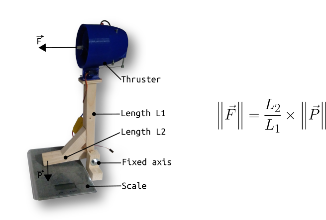
To get all the required data, I increased the throttle gradually while recording the force on the scale and the power consumption. This operation is repeated several times for each fan, to make sure the the data is consistent. The following figure is the final graph with all the efficiency data I gathered.
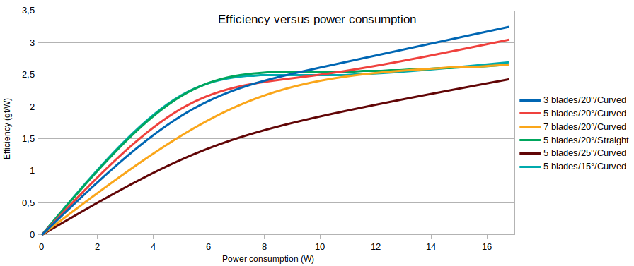
This tells us that, in my case, the ideal combination of parameters is 3 curved 20° pitch blades. Interestigly, this matches with the theoretical results: a smaller number of blades leaves more time between the blades, meaning that they have to deal with less turbulence. As the rotation speed grows, this factor should become more and more significant. The straight design seem to bend a lot although its rigidity is identical at rest.
The other piece of information to consider is the maximum thrust output of each configuration.
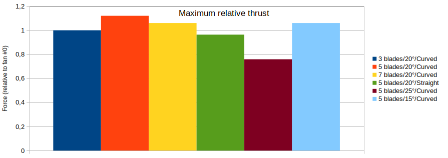
The 3 curved 20° pitch fan generates the most thrust. The choice between efficiency and maximum power is often a compromise. Like before, the higher pitched blades are the worst performer.
Unfortunately, reverse thrust only generates a few grams of force. Although a larger volume of air seem to be diverted forward, the rest gets speed up (probably due to the Venturi effect). This balances the forces resulting in very low backward force. Hence, the thrust reversal is pointless on this design.
Conclusion
It should be noted that in a real operating situation, the relative speed between the air and the motor would not be zero. Hence, static thrust is quite different from dynamic thrust. For instance, the ideal pitch of the blades depend on this relative speed.
The next step is to use this data to build a motor mounted to an RC aircraft capable of flying.
Download
Click on this button to download the archive contain the CAD (SolidWorks, STEP and OpenSCAD) and the 3D-print files (STL):
Author: Charles Grassin
What is on your mind?
Sorry, comments are temporarily disabled.
#1 Shreyas da boi
on December 16 2021, 13:01
#2 Tim Newman
on December 19 2021, 8:08
#3 James
on September 5 2022, 20:46
#4 Quinquestriatus
on October 19 2022, 20:24